Anesthetic waste gas extraction device for anesthesia department

A waste gas and departmental technology, which is applied in the direction of dust removal, cleaning methods and utensils, and separation of dispersed particles, can solve problems such as complex structures, and achieve the effect of increasing sterilization time, increasing flow distance, and improving sterilization effect

Inactive Publication Date: 2020-06-02
李庆磊
View PDF1 Cites 1 Cited by
  • Summary
  • Abstract
  • Description
  • Claims
  • Application Information

AI Technical Summary

Problems solved by technology

The structure of the program is complex and there are improvements

Method used


Image

  • Anesthetic waste gas extraction device for anesthesia department
  • Anesthetic waste gas extraction device for anesthesia department
  • Anesthetic waste gas extraction device for anesthesia department

Examples


Embodiment 1

[0027] The technical solution of the present invention will be further described below in conjunction with the accompanying drawings.

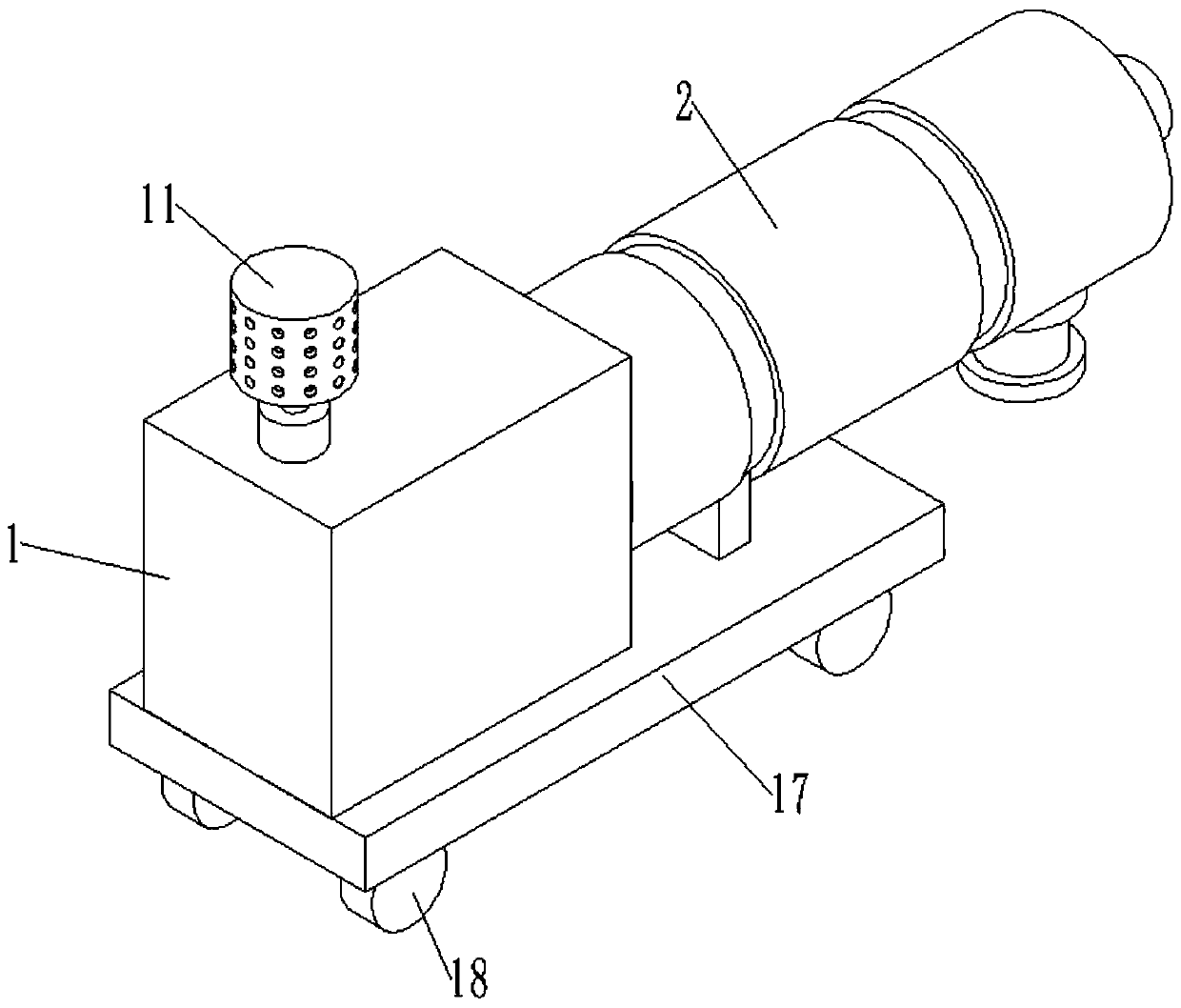
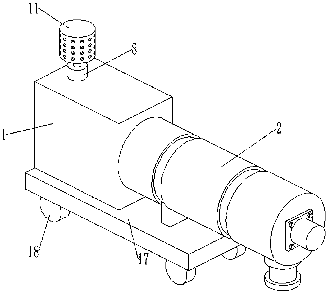
[0028] Such as figure 1 with figure 2 As shown, an anesthesia waste gas extraction device for an anesthesia department includes a purification box 1 and a sterilization cylinder 2. The purification box 1 is used to purify the anesthesia waste gas, and the bacteria removal box is used to sterilize the anesthesia waste gas.

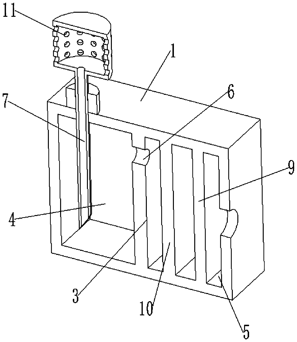
[0029] Such as image 3 with Figure 4 As shown, the purification box 1 is provided with a partition plate 3, and the partition plate 3 divides the inner space of the purification box 1 into a first chamber 4 and a second chamber 5; the partition plate 3 is provided with a communication hole 6, The communication hole 6 communicates with the first chamber 4 and the second chamber 5; the first chamber 4 is provided with sodium hydroxide solution, the purification box 1 is provided with an air inlet pipe 7, and the air inl...

Embodiment 2

[0038] Embodiment 2 is a further improvement on Embodiment 1.

[0039] Such as Figure 5 with Image 6 As shown, deflector 15 and silencer pipe 16 are arranged in the sterilization cylinder 2, and the two ends of silencer pipe 16 are open and coaxially arranged with the sterilization chamber, between the pipe wall of silencer pipe 16 and the inner peripheral wall of the sterilization chamber There are intervals, the pipe wall of the muffler pipe 16 is provided with a plurality of muffler holes, the muffler pipe 16 is spirally wound with a deflector 15, one side of the deflector 15 is located in the muffler pipe 16, and the other side of the deflector 15 It abuts against the inner peripheral wall of the sterilization cavity.

[0040] The setting of the deflector 15 will guide the anesthesia waste gas to form a spiral flow path when it flows in the sterilization chamber. Compared with the traditional straight flow path, it increases the flow path of the anesthesia waste gas an...


PUM


Abstract

The invention relates to an anesthetic waste gas extraction device for the anesthesiology department. The anesthetic waste gas extraction device comprises a purification box and a sterilization cylinder; a partition plate is arranged in the purification box and divides the internal space of the purification box into a first chamber and a second chamber; a communicating hole is formed in the partition plate and communicates the first cavity with the second cavity; a sodium hydroxide solution is arranged in the first cavity, a gas inlet pipe is arranged on the purification box, a gas pump is arranged on the gas inlet pipe, one end of the gas inlet pipe is inserted into the sodium hydroxide solution, and an adsorption layer is arranged in the second cavity; and the sterilization cylinder is provided with a sterilization cavity, the sterilization cylinder is provided with a gas inlet and a discharge outlet, the gas inlet and the discharge outlet are both communicated with the sterilizationcylinder, the gas inlet is communicated with the second cavity, the sterilization cylinder is provided with an ultraviolet lamp, and the lamp tube of the ultraviolet lamp is located in the sterilization cylinder and extends in the length direction of the sterilization cylinder.

Description

technical field [0001] The invention relates to the technical field of anesthesia equipment, in particular to an anesthesia waste gas extraction device for an anesthesia department. Background technique [0002] With the gradual increase in the application of inhaled anesthetics in the operating room, the anesthetic gas or vapor diffused in the operating room during the operation will inevitably cause air pollution in the operating room environment. Long-term exposure to the polluted environment of trace amounts of anesthesia exhaust gas can have adverse effects on the physical and mental health of operating room staff, especially female staff during pregnancy and lactation, which may cause spontaneous abortion, fetal deformation and reduced fertility danger. The anesthesia exhaust gas pollution and its hazards in the operating room have attracted widespread attention. Reducing the anesthesia exhaust gas pollution in the operating room and strengthening the health protectio...

Claims


Application Information

Patent Timeline
Patent Type & Authority Applications(China)
IPC IPC(8): B01D53/78B01D53/74B01D53/62B08B15/00B01D53/26B01D53/04
CPCB01D53/04B01D53/26B01D53/62B01D53/74B01D53/78B08B15/00
Inventor 李庆磊
Owner 李庆磊
Why Eureka
Try Eureka