
Composite loop heat pipe and composite loop heat pipe heat exchange assembly

A technology for heat exchange components and heat pipe heat exchangers, which is applied in the field of heat exchange and heat pipes, can solve the problems of the working position being affected by gravity, the heat transfer capacity is not large enough, the volume heat capacity is small, etc., and achieves compact structure, low cost and small volume. Effect

Pending Publication Date: 2020-05-29
长沙馨麓能源科技有限公司
View PDF0 Cites 1 Cited by
  • Summary
  • Abstract
  • Description
  • Claims
  • Application Information

AI Technical Summary

Problems solved by technology

[0002] At present, heat pipes and heat pipe heat exchangers are widely used in industrial applications such as heat transfer and heat dissipation due to their high heat transfer efficiency, fast heat transfer speed, high pressure bearing, and energy saving. However, traditional heat pipes and heat pipe heat exchangers There are shortcomings such as insufficient heat transfer capacity, large volume, and complicated manufacturing process.
The plate-fin heat exchanger is integrally brazed with aluminum plate and aluminum fins. It is small in size, light in weight, and high in heat transfer efficiency. However, it has disadvantages such as weak pressure bearing capacity and easy leakage.
Some people in the industry try to make heat pipe heat exchangers using a manufacturing process similar to plate-fin heat exchangers. Most of them are connected at the lower end, which has shortcomings such as insufficient heat transfer capacity, small volume heat capacity, and the working position is affected by gravity. How to improve this It is a technical difficulty to be solved urgently in the industry to improve the heat transfer capacity of the heat exchanger and make its working orientation not affected by gravity.

Method used


Image

  • Composite loop heat pipe and composite loop heat pipe heat exchange assembly
  • Composite loop heat pipe and composite loop heat pipe heat exchange assembly
  • Composite loop heat pipe and composite loop heat pipe heat exchange assembly

Examples


Embodiment 1

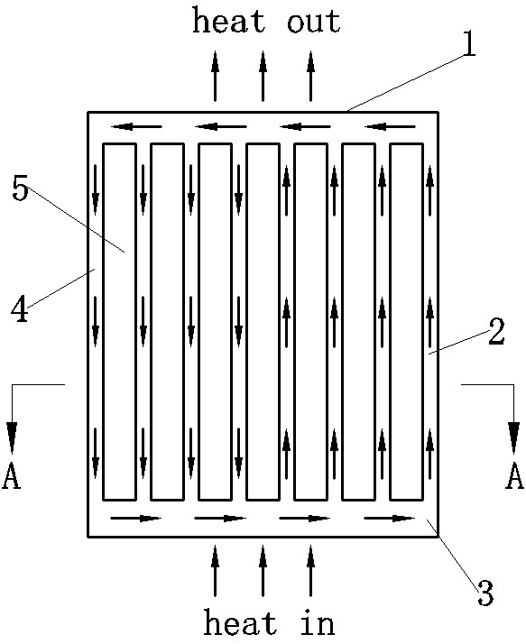
[0047] Embodiment 1: as figure 1 As shown, the composite loop heat pipe is composed of header A1, evaporation channel 2, header B3, and condensation channel 4, and evaporation channel 2 or condensation channel 4 is composed of figure 2 The porous channel composition shown is that the porous channels are arranged side by side with channel gaps 5 in between. The inner wall of the porous channel is smooth or provided with internal teeth, Figure 5 for figure 2 An example of an internal tooth enlargement of a porous channel. When working, heat enters the composite loop heat pipe from the heating section (such as the bottom plate or the lower half of the composite loop heat pipe), and the working fluid is heated and evaporated, and the heat is brought to the cooling section (such as the upper top plate or the composite loop heat pipe) along the evaporation channel 2 The upper part of the heat pipe) and dissipate away from the cooling section. At this time, the working fluid co...

Embodiment 2

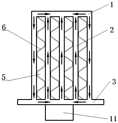
[0048] Embodiment 2: as image 3 and Figure 4 As shown, the porous channel in the composite loop heat pipe is not limited to only one header A described in Embodiment 1, the header A of this embodiment is divided into four, and the header B shares one, and its working principle Same as Example 1. The inner wall of the porous channel is smooth or provided with internal teeth, Figure 5 also for Figure 4 An example of an internal tooth enlargement of a porous channel.

Embodiment 3

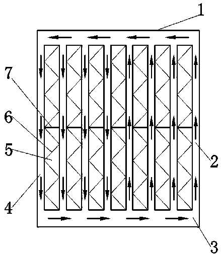
[0049] Embodiment 3: as Figure 6 As shown, the composite loop heat pipe and its heat exchange components are air-air heat exchangers, which are composed of header A1, evaporation channel 2, header B3, condensation channel 4, fins 6, and partitions 7. The channel gap Fins 6 are arranged inside 5, so that the fins 6 fit closely with the porous channel. The partition plate 7 divides the heat exchange area into a heating section and a cooling section. The hot air enters the channel gap 5 from the heating section, and the fins 6 are heated to transfer heat. For the heating section of the porous channel, the working fluid is heated and evaporates to form the evaporation channel 2 along the channel with small resistance, which is transferred to the header A1, the heat is transferred from the cooling section to the fin 6, and then transferred to the cold air, and the working fluid releases heat and condenses into condensation Channel 4 realizes the return flow of working fluid, there...


PUM


Abstract

The invention relates to a composite loop heat pipe and a composite loop heat pipe heat exchange assembly. The composite loop heat pipe comprises a header box A, a header box B, evaporation channels and condensation channels. One ends of the evaporation channels and one ends of the condensation channels are connected with the header box A, and the other ends of the evaporation channels and the other ends of the condensation channels are connected with the header box B. The header box A, the header box B, the evaporation channels and the condensation channels form a loop, and a composite loop heat pipe structure is formed. The internal channels of the composite loop heat pipe are in a vacuum or negative-pressure state, and a working medium playing a role of phase-change heat transfer is sealed in the internal channels of the composite loop heat pipe. Fins or heat source channels or cold source channels are attached between the adjacent evaporation channels or the adjacent condensation channels of the composite loop heat pipe to form the heat exchange assembly. The heat exchange assembly automatically achieves the gas-gas heat exchange or gas-liquid heat exchange effect. The composite loop heat pipe and the composite loop heat pipe heat exchange assembly have the advantages of high heat exchange efficiency, large heat flux density, high heat exchange speed, high pressure bearingcapacity, light weight, stable structure, good frost resistance, safe operation and the like and belong to novel heat exchange elements.

Description

technical field [0001] The invention relates to the technical field of heat exchange and heat pipes, in particular to a composite loop heat pipe and a heat exchange assembly thereof. Background technique [0002] At present, heat pipes and heat pipe heat exchangers are widely used in industrial applications such as heat transfer and heat dissipation due to their high heat transfer efficiency, fast heat transfer speed, high pressure bearing, and energy saving. However, traditional heat pipes and heat pipe heat exchangers There are shortcomings such as insufficient heat transfer capacity, large volume, and complicated manufacturing process. The plate-fin heat exchanger is integrally brazed with aluminum plate and aluminum fins. It is small in size, light in weight, and high in heat transfer efficiency. However, it has disadvantages such as weak pressure bearing capacity and easy leakage. Some people in the industry try to use a manufacturing process similar to plate-fin heat ...

Claims


Application Information

Patent Timeline
Patent Type & Authority Applications(China)
IPC IPC(8): F28D15/02F28D15/04
CPCF28D15/0266F28D15/043
Inventor 江乐新
Owner 长沙馨麓能源科技有限公司
Learn More