
Anti-loosening tail gas treatment device based on magnetoelectric principle

An exhaust gas treatment and anti-loosening technology, which is applied in exhaust gas treatment, electromechanical devices, power devices, etc., can solve problems that affect the efficiency of exhaust gas treatment, loose fixing bolts, and exhaust gas leakage, so as to improve the efficiency of exhaust gas treatment and ensure fastening performance, the effect of preventing exhaust gas leakage

Active Publication Date: 2020-05-22
冯赵宝
View PDF6 Cites 3 Cited by
  • Summary
  • Abstract
  • Description
  • Claims
  • Application Information

AI Technical Summary

Problems solved by technology

[0003] When the current automobile exhaust treatment device is installed, most of them are fixedly connected to the automobile exhaust pipe through the flange, and then the two are relatively fixed by fixing bolts and nuts. However, when the car is running, the body will vibrate violently, causing the fixing bolts to It will loosen under the action of constant vibration, which may cause the exhaust gas treatment device to fall off, and the untreated exhaust gas will leak into the atmosphere and pollute the atmosphere
It is not conducive to environmental protection, and the current air flow in the exhaust gas treatment device is mostly realized by extrusion, resulting in the treated gas also staying in the treatment device, occupying the filter space of the treatment device, and affecting the treatment efficiency of the exhaust gas

Method used


Image

  • Anti-loosening tail gas treatment device based on magnetoelectric principle
  • Anti-loosening tail gas treatment device based on magnetoelectric principle
  • Anti-loosening tail gas treatment device based on magnetoelectric principle

Examples


Embodiment Construction

[0020] The technical solutions in the embodiments of the present invention will be clearly and completely described below in conjunction with the accompanying drawings in the embodiments of the present invention. Obviously, the described embodiments are only some of the embodiments of the present invention, not all of them. Based on the embodiments of the present invention, all other embodiments obtained by persons of ordinary skill in the art without creative work all belong to the protection scope of the present invention.

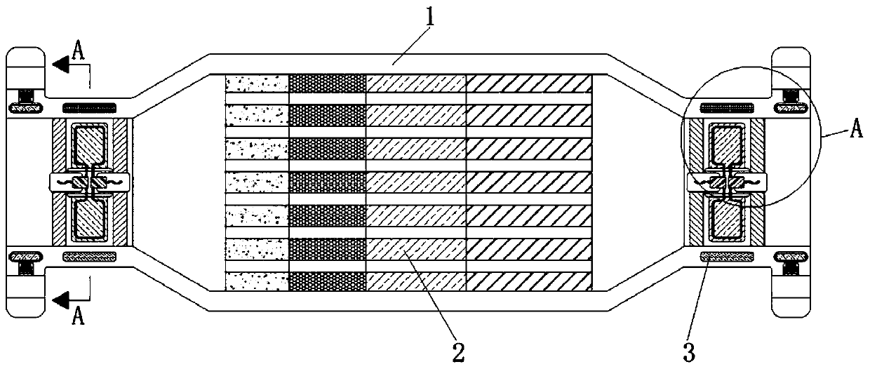
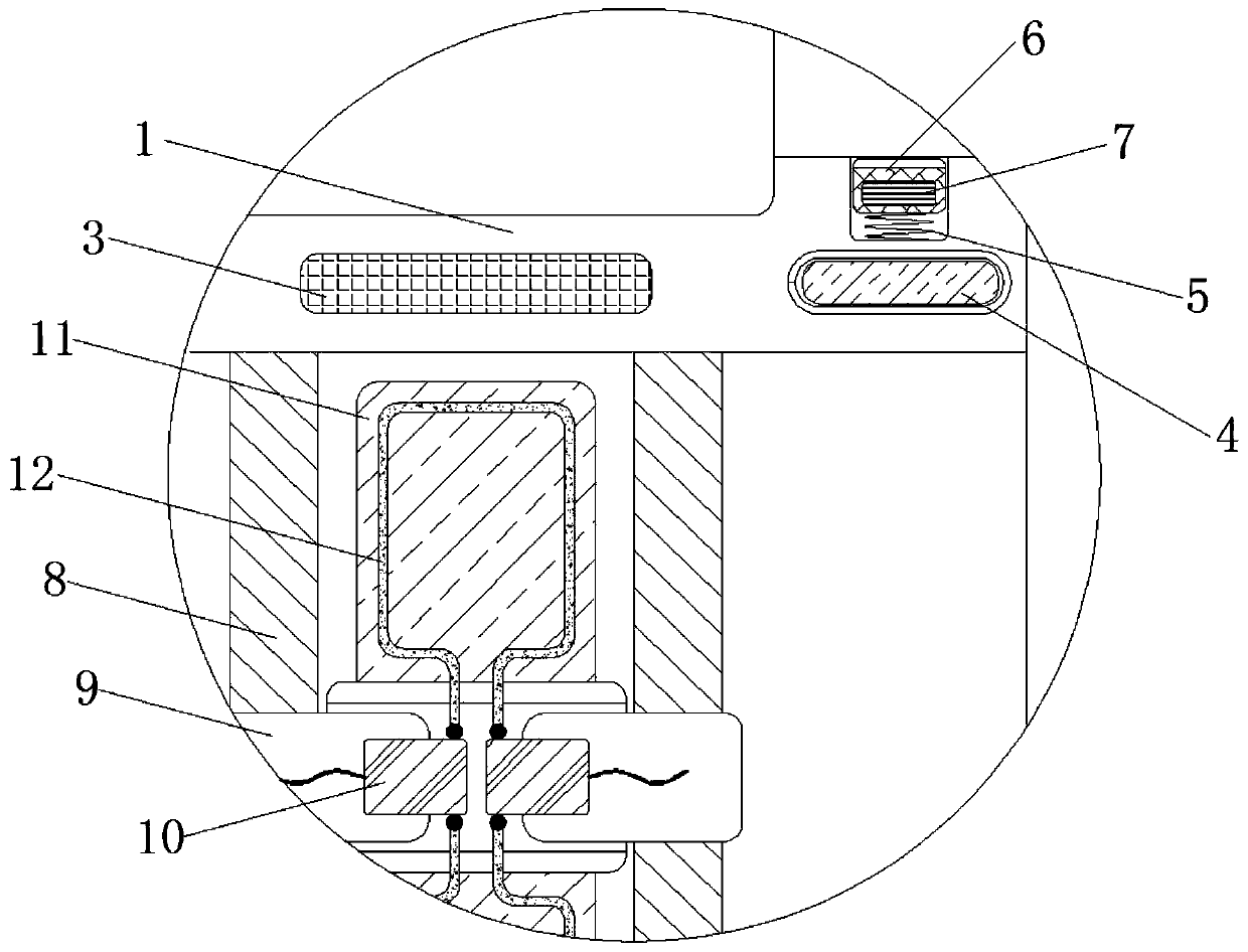
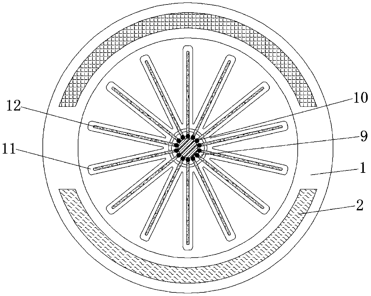
[0021] see Figure 1-5 , an anti-loose exhaust gas treatment device based on the principle of magnetoelectricity, including a housing 1, the housing 1 plays the role of fixing various components, the material of the housing 1 is steel and the shape of the housing 1 is cylindrical The magnetism of the opposite surface of the magnetic ring 3 is opposite and the material of the magnetic ring 3 is a rubidium magnet material. The magnetism on the outside of t...


PUM


Abstract

The invention discloses an anti-loosening tail gas treatment device based on a magnetoelectric principle, and relates to the technical field of air pollution control. The anti-loosening tail gas treatment device comprises a shell body, wherein a three-phase catalyst is fixedly connected to the middle of the shell body, two symmetrical magnetic rings are fixedly connected to the inner walls of thetwo ends of the shell body correspondingly, electromagnets are fixedly connected to the inner walls of the two ends of the shell body correspondingly, and uniformly-distributed springs are fixedly connected to the outer sides of the two sides of the shell body. According to the anti-loosening tail gas treatment device based on the magnetoelectric principle, through cooperative use of a limiting block and a limiting groove, tail gas can drive a closed coil in an impeller to continuously cut magnetic induction lines of the magnetic rings when the device is in use, current is generated accordingto the magnetoelectric principle and conveyed to the electromagnets, so that the electromagnets generate magnetism; and in addition, the limiting block moves towards the outer side and is clamped withthe limiting groove according to the principle that two like magnetic poles repel each other, so that an effect of preventing a fixing screw from loosening is achieved, tail gas leakage is effectively prevented, and fixing tightness of a tail gas treater is guaranteed.

Description

technical field [0001] The invention relates to the technical field of air pollution control technology, in particular to an anti-loosening tail gas treatment device based on the principle of magnetoelectricity generation. Background technique [0002] In recent years, the seriousness of air pollution has been paid more and more attention. According to expert statistics, polluting gases such as carbon dioxide, nitrogen monoxide, and carbon monoxide produced by human life have seriously damaged the atmospheric ozone layer. If this continues, one day The ozone layer will disappear completely. At that time, ultraviolet rays will directly irradiate the surface of the earth. At that time, human skin will be severely burned, making the earth a planet that is not easy for humans to live on, and even the earth will perish. Therefore, the world is vigorously promoting air pollution. The development of control technology, and the automobile exhaust treatment device is one of the treat...

Claims


Application Information

Patent Timeline
IPC IPC(8): F01N3/28F01N5/04F01N13/18B60K13/04H02K7/18
CPCB60K13/04F01N3/28F01N3/2882F01N5/04F01N13/1838F01N2240/05F01N2260/06F01N2290/04H02K7/1823Y02T10/12
Inventor 冯赵宝
Owner 冯赵宝
Learn More