Separation method of mold material with glass-transition temperature

A glass transition and separation method technology, applied in electrical components, semiconductor/solid-state device manufacturing, circuits, etc., can solve the problems of low LED package yield, deformation of LED package, bulging of the middle part, etc., to achieve high cutting Separation yield, no quality loss, right size effect

Active Publication Date: 2020-05-19
HAIDIKE NANTONG OPTOELECTRONICS TECH CO LTD
View PDF11 Cites 0 Cited by
  • Summary
  • Abstract
  • Description
  • Claims
  • Application Information

AI Technical Summary

Problems solved by technology

Moreover, this extrusion force will extend laterally to both sides and act on each adjacent package in turn, which will easily cause severe deformation of the LED package after cutting and separation under the action of multiple extrusion stresses, and after cutting It is easy to cause the middle part to bulge, and it is impossible to realize the subsequent separation after the next step of cutting, and finally cause the yield rate of the LED package to be cut and separated to be low

Method used


Image

  • Separation method of mold material with glass-transition temperature
  • Separation method of mold material with glass-transition temperature
  • Separation method of mold material with glass-transition temperature

Examples


Embodiment

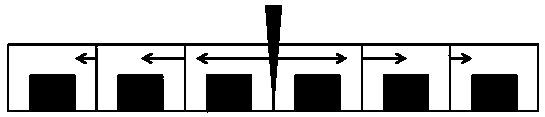
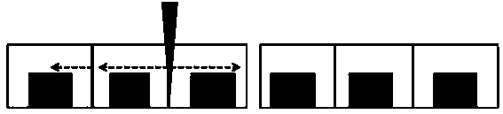
[0036] This embodiment has the separation method of the mold material of glass transition temperature, in this embodiment, the mold material with glass transition temperature is an LED light source with a transparent or translucent layer, such as Figure 8 As shown, the LED light source in the LED light source array includes an LED chip body and a silicone encapsulation layer covering the top and side surfaces of the LED chip body. The separation method includes:

[0037] Step 1: Film expansion process: first, heat and keep warm the uncut LED light source semi-finished substrate. The uncut LED light source semi-finished substrate includes a number of chips distributed in an array, and the package that is packaged with the chips distributed in the array as a whole layer; the heating and holding temperature range in the film expansion process meets the following conditions:

[0038] (1) The modulus of the encapsulation layer changes with its own temperature as a function expressio...


PUM

PropertyMeasurementUnit
glass transition temperatureaaaaaaaaaa

Abstract

The invention relates to a separation method of a mold material with a glass-transition temperature. The method comprises the following steps: cutting an uncut polymer mold material in a stretching state at a specific temperature while keeping the elastic state of the mold material, thereby obtaining a cut mold material monomer with a smooth section and a proper size under the shrinkage action ofthe cut monomer mold material. The separation method has the advantages of being obvious in stress release effect, free of mass loss and high in cutting separation yield.

Description

technical field [0001] The invention belongs to the technical field of semiconductor packaging, in particular to a method for separating mold materials with a glass transition temperature. Background technique [0002] At present, in the process of separating most of the mold materials of polymer materials, the commonly used methods mainly include the following: laser cutting with radiant energy, high-speed rotating flywheel cutting, tool splitting and punching. Among them, laser cutting is a non-contact cutting method. Its principle is to obtain high energy density after laser energy is optically focused, and then directly vaporize the mold material along the cutting path of the mold material to separate and obtain a single mold material. The focal point temperature generated by the laser is too high, which will cause deformation of the mold material, and the cost is very high. However, the cost of tools and equipment used in flywheel cutting is high. Due to the need for l...

Claims


Application Information

Patent Timeline
Patent Type & Authority Applications(China)
IPC IPC(8): H01L21/67H01L33/48
CPCH01L33/48H01L21/67092H01L21/67248H01L2933/0033
Inventor 王书昶孙智江宋健
Owner HAIDIKE NANTONG OPTOELECTRONICS TECH CO LTD
Why Eureka
Try Eureka