
Apparatus and method for treatment of process vapours coming from vacuum concentration section of urea plant

A technology of vacuum concentration and urea equipment, applied in the direction of vacuum distillation, chemical instruments and methods, separation methods, etc., to achieve the effect of reducing the flow rate and reducing the total intake

Pending Publication Date: 2020-05-15
SAIPEM SPA
View PDF3 Cites 0 Cited by
  • Summary
  • Abstract
  • Description
  • Claims
  • Application Information

AI Technical Summary

Problems solved by technology

However, in vacuum systems of the type described above, the purge gases are vented to the atmosphere and there is not enough pressure to transport them to the final processing system

Method used


Image

  • Apparatus and method for treatment of process vapours coming from vacuum concentration section of urea plant
  • Apparatus and method for treatment of process vapours coming from vacuum concentration section of urea plant
  • Apparatus and method for treatment of process vapours coming from vacuum concentration section of urea plant

Examples


Embodiment Construction

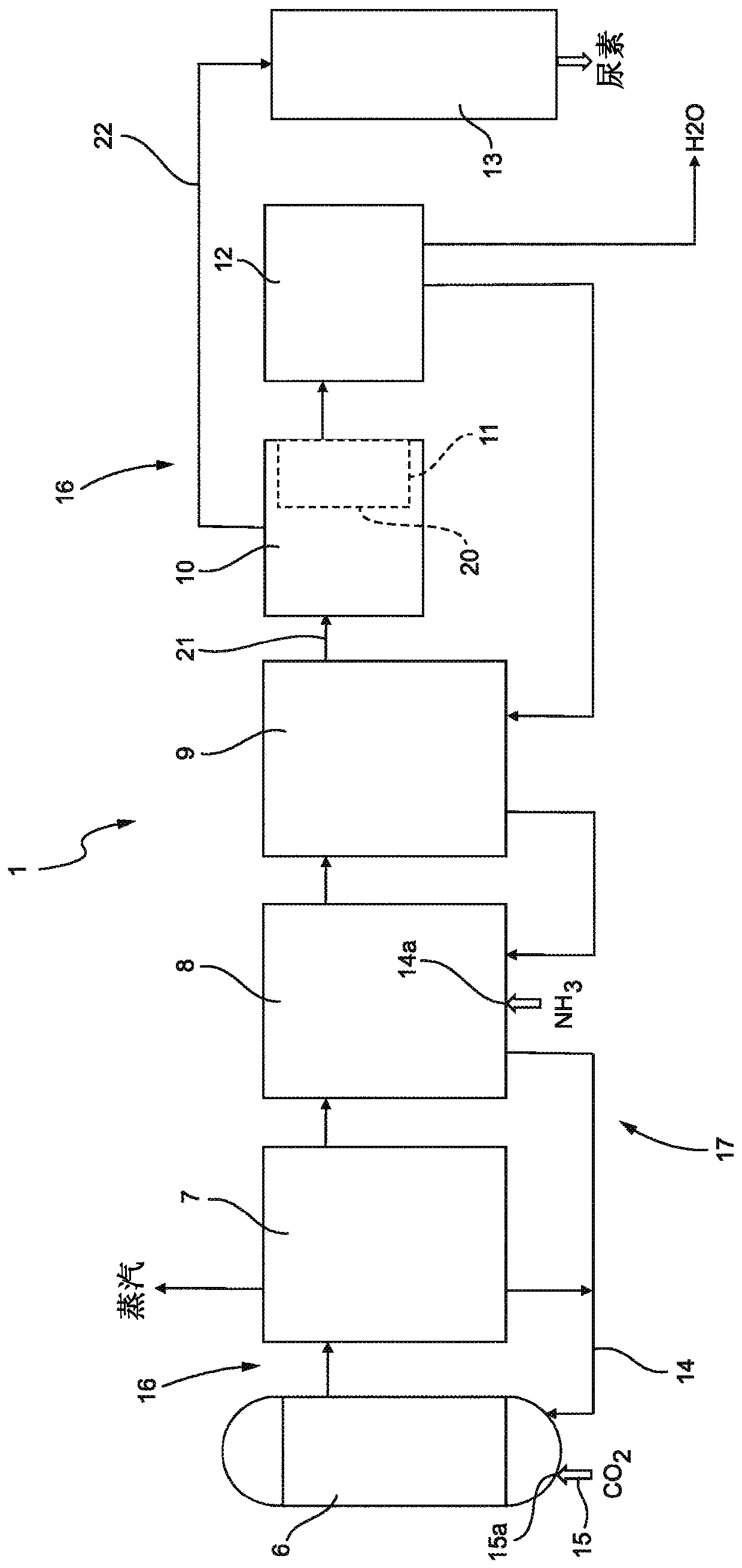
[0055] figure 1 A urea plant 1 (ie a plant for producing urea) is shown in a very schematic way.

[0056] The overall configuration of the urea plant 1 can be of one of several types, as is the urea production process implemented in the plant.

[0057] Here, reference is made by way of example only to a urea production plant / process according to the known "Snamprogetti" technology. It should be understood that the invention is also applicable to other urea production plants / processes using a vacuum concentration section or in any case at least one vacuum system.

[0058] In the non-limiting configuration shown, the urea plant 1 includes, but is not limited to: a urea synthesis reactor 6, in which the urea synthesis reaction from ammonia and carbon dioxide takes place; recovery sections 7, 8 and 9, in particular high pressure recovery section 7, Medium-pressure recovery section 8 and low-pressure recovery section 9, in which the urea solution produced in reactor 6 is graduall...


PUM


Abstract

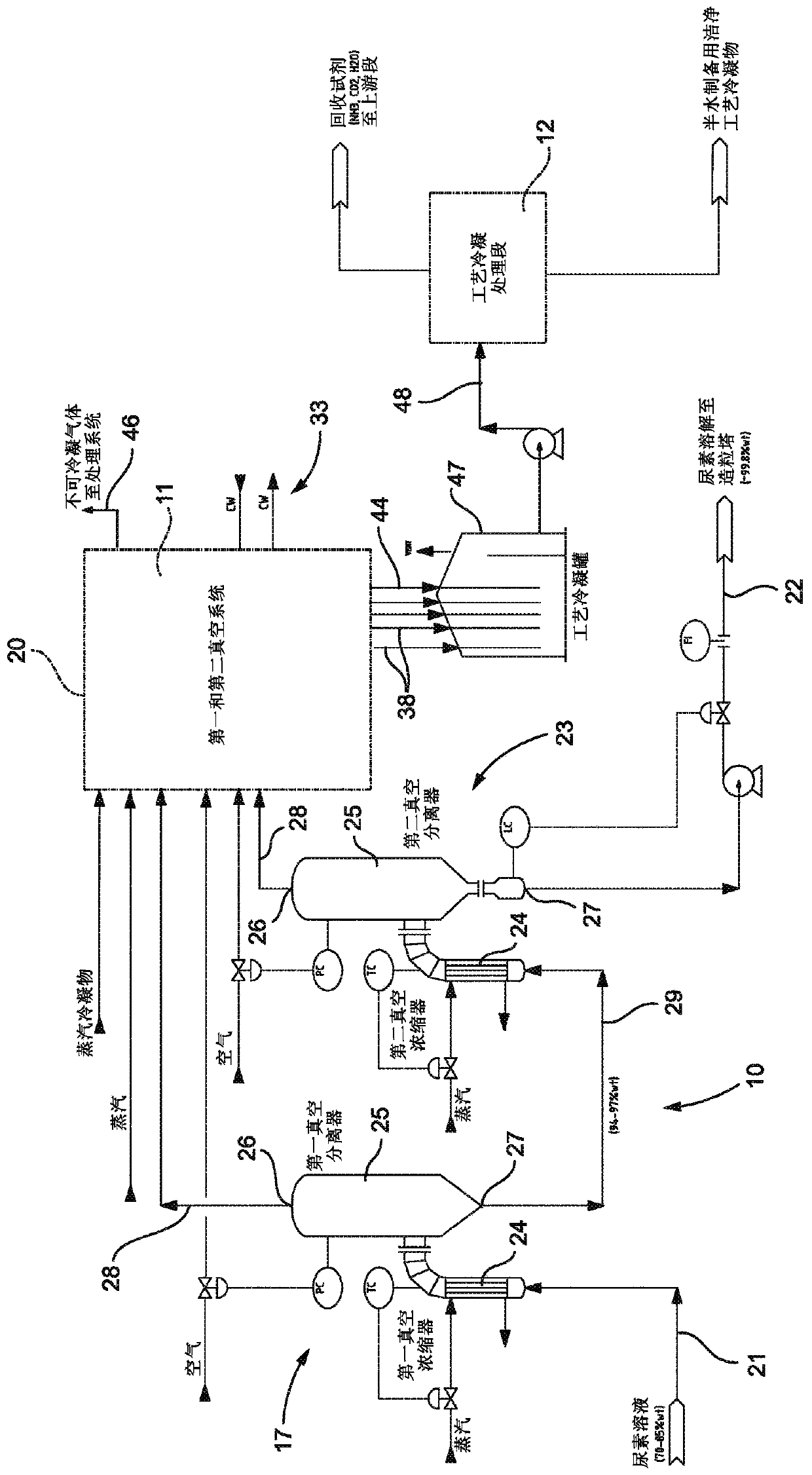
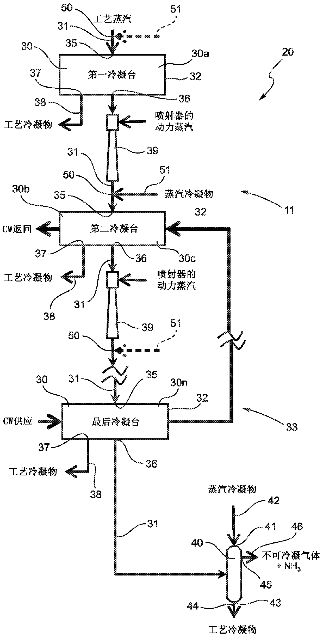
An apparatus (20) for treatment of process vapours coming from a vacuum concentration section (10) of a urea plant, comprising a vacuum system (11) having a plurality of successive condensation stages(30), connected in series by respective line portions (31) and crossed in series by process vapours to be treated; the apparatus (20) has at least one primary steam condensate inlet (50) for feedingsteam condensate to the vacuum system (11) and positioned, with reference to a circulation direction of the process vapours in the vacuum system (11), upstream of at least one selected condensation stage (30), or in at least one selected condensation stage (30).

Description

[0001] Cross References to Related Applications [0002] This patent application claims priority from Italian Patent Application No. 102017000121364 filed on October 25, 2017, the entire disclosure of which is incorporated herein by reference. technical field [0003] The invention relates to a plant and a method for treating process vapors from the vacuum concentration section of a urea plant. Background technique [0004] Urea is known to be produced on an industrial scale by a process based on the reaction between carbon dioxide and ammonia at high temperature and pressure to form ammonium carbamate (intermediate), followed by a decomposition reaction of ammonium carbamate to provide urea and water of. [0005] The overall synthetic reaction is an equilibrium reaction adversely affected by excess water; since it is an equilibrium reaction, the reaction products must be separated from intermediates and unconverted reagents. [0006] In general, the urea synthesis reactio...

Claims


Application Information

Patent Timeline
Patent Type & Authority Applications(China)
IPC IPC(8): B01D5/00B01D53/00B01D53/14B01D53/18C07C273/16
CPCB01D53/002B01D53/14B01D53/1406C07C273/16B01D2252/103B01D2257/406Y02P20/582B01D3/10
Inventor 克里斯蒂娜·切罗内雅各布·切德拉蒂
Owner SAIPEM SPA
Learn More