
Method of generating trigger signal for controlling multimedia interface

A technology of multimedia interface and trigger signal, applied in the direction of signal generation/distribution, image communication, color TV components, etc., can solve the problems of high cost and unoptimized multimedia interface control.

Active Publication Date: 2020-05-12
STMICROELECTRONICS (ROUSSET) SAS
View PDF16 Cites 0 Cited by
  • Summary
  • Abstract
  • Description
  • Claims
  • Application Information

AI Technical Summary

Problems solved by technology

This can represent large amounts of data and requires buffer memory with high storage capacity, which is often expensive
[0014] In general, the control of the multimedia interface is not optimized due to the constraints imposed by the synchronization points generated by the multimedia interface

Method used


Image

  • Method of generating trigger signal for controlling multimedia interface
  • Method of generating trigger signal for controlling multimedia interface
  • Method of generating trigger signal for controlling multimedia interface

Examples


Embodiment Construction

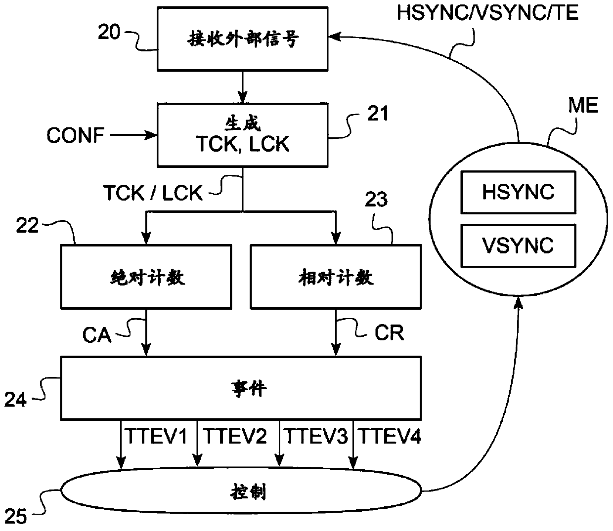
[0062] figure 2 An example of a method for creating a trigger signal TTEVi (1≤i≤4) for controlling 25 electronic modules ME is shown.

[0063] This method is suitable for controlling any type of electronic module that may require several synchronization points.

[0064] In particular, controlling multimedia interface electronic modules presents a significant requirement for being able to utilize several synchronization points. In the following, therefore, reference will be made to electronic modules of the multimedia interface module type. A multimedia interface is to be understood in particular as meaning a display interface of the CCD or CMOS sensor type, such as a TFT-LCD or AMOLED screen, as well as a video image capture interface.

[0065] The method includes generating 21 digital timing signals TCK, LCK to emulate synchronization signals HSYN, VSYNC inside the module. The timing signal will be used as a clock signal whose period will time the incrementing or decremen...


PUM


Abstract

The invention relates to a method for generating a trigger signal for controlling a multimedia interface. A system includes an electronic module and an integrated circuit external to the electronic module. The integrated circuit is configured to generate a digital timing signal emulating a first synchronization signal, the first synchronization signal is internal to the module and is unavailable external to the module, and a trigger signal is generated based on the digital timing signal. The controller is configured to independently and autonomously perform a control operation of the electronic module at the time triggered by the trigger signal.

Description

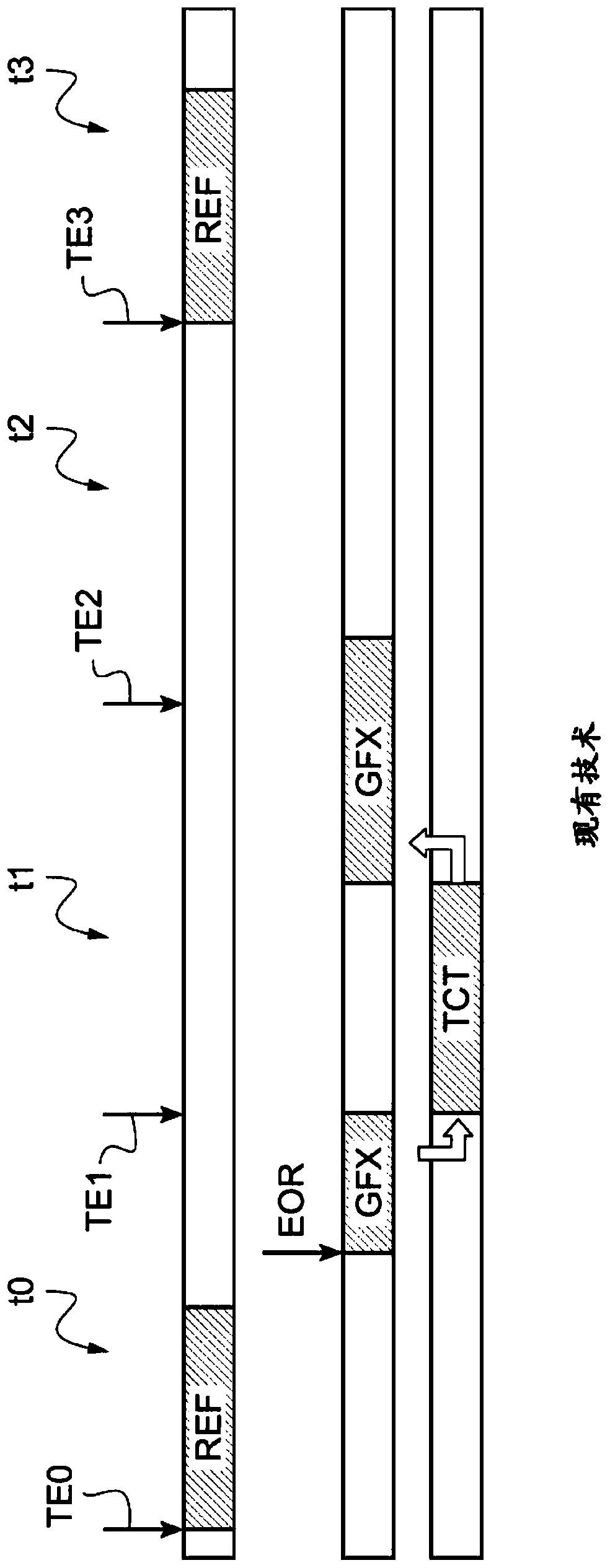
[0001] Cross References to Related Applications [0002] This application claims priority from French Patent Application No. 1860188 filed November 6, 2018, which is hereby incorporated by reference. technical field [0003] Implementation modes and embodiments relate to methods of generating trigger signals for controlling multimedia interfaces. Background technique [0004] Typically, synchronization of software or hardware operations using electronic modules is performed statically using interrupt signals generated by the modules. The module cannot provide any interrupt signal. [0005] In the example of a multimedia interface electronic module, typically when a given row of an image frame is being processed by the multimedia interface, an interrupt signal is generated for each image. [0006] As a result, graphics interfaces typically have only one synchronization point (also denoted by the term "interrupt signal") per frame. [0007] Now, if figure 1 As shown with...

Claims


Application Information

Patent Timeline
Patent Type & Authority Applications(China)
IPC IPC(8): H04N5/04H04N5/06H04N5/765
CPCH04N5/04H04N5/06H04N5/765G06F1/04G06F3/0416G09G5/006G09G2310/08H04N23/80
Inventor O·费朗
Owner STMICROELECTRONICS (ROUSSET) SAS
Learn More