
Antenna assembly and electronic equipment

An antenna assembly and antenna module technology, which is applied in the electronic field to achieve the effects of improving the reflection coefficient, increasing the gain and increasing the antenna gain

Active Publication Date: 2020-05-12
GUANGDONG OPPO MOBILE TELECOMM CORP LTD
View PDF3 Cites 8 Cited by
  • Summary
  • Abstract
  • Description
  • Claims
  • Application Information

AI Technical Summary

Problems solved by technology

However, applying mmWave antennas to electronic devices still faces many technical and design challenges

Method used


Image

  • Antenna assembly and electronic equipment
  • Antenna assembly and electronic equipment
  • Antenna assembly and electronic equipment

Examples


Embodiment Construction

[0031] The following will clearly and completely describe the technical solutions in the embodiments of the application with reference to the drawings in the embodiments of the application. Apparently, the described embodiments are only some of the embodiments of the application, not all of them. The embodiments listed in this application may be properly combined with each other.

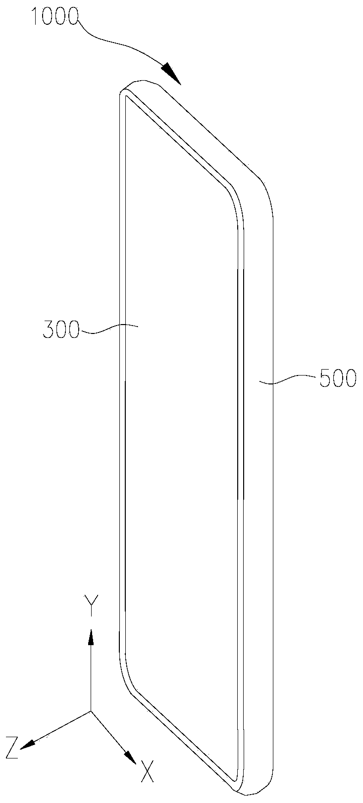
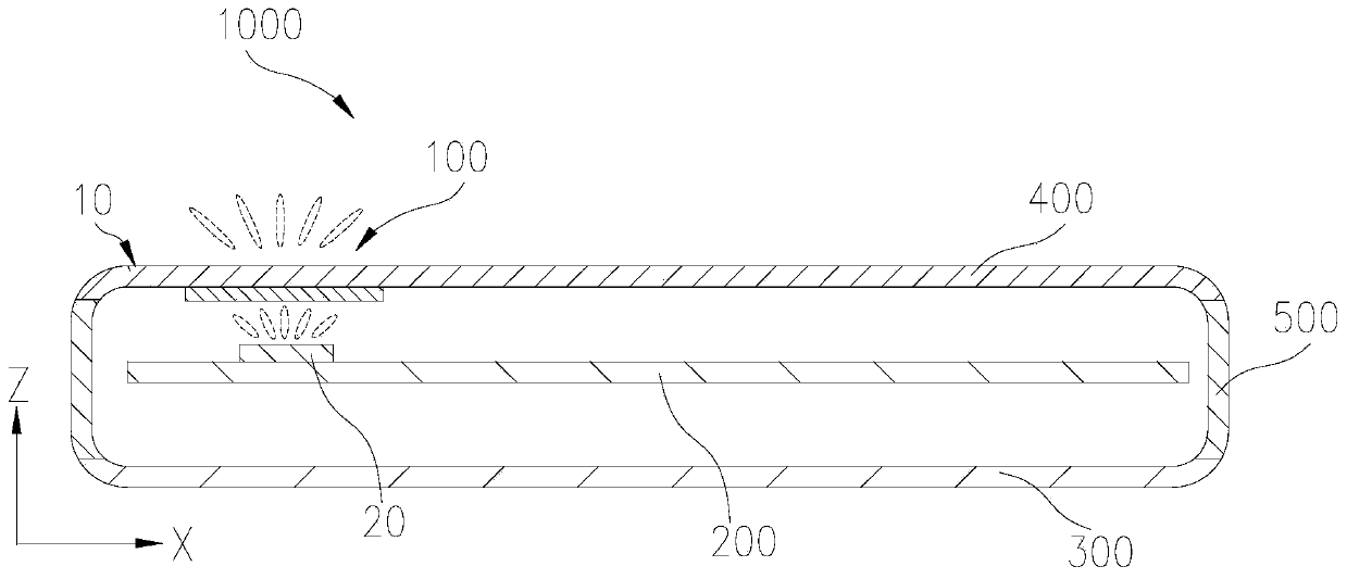
[0032] Please refer to figure 1 , figure 1 It is a schematic structural diagram of an electronic device provided in an embodiment of the present application. The electronic device 1000 may be a telephone, a television, a tablet computer, a mobile phone, a camera, a personal computer, a notebook computer, a vehicle-mounted device, a headset, a watch, a wearable device, a base station, a vehicle-mounted radar, a customer premise equipment (Customer Premise Equipment, CPE), etc. A device capable of sending and receiving electromagnetic waves. Taking the electronic device 1000 as a mobile phone as an...


PUM


Abstract

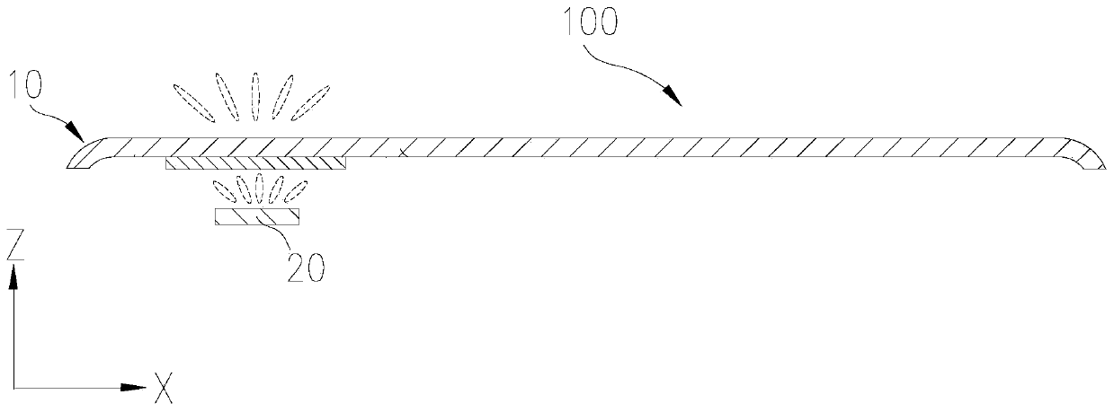
The invention provides an antenna assembly and electronic equipment, and the antenna assembly comprises an antenna module which comprises a radiation part and a grounding part which are oppositely arranged, wherein the surface, facing the radiation part, of the grounding part is a first reflection surface for reflecting a radio frequency signal; a radome which is arranged at one side, deviating from the grounding part, of the radiation part, and covers the radiation part, wherein the radome comprises at least two dielectric layers, wherein an interface between the adjacent dielectric layers forms a second reflecting surface used for reflecting at least part of radio frequency signals. The first reflecting surface, the second reflecting surface and a part between the first reflecting surface and the second reflecting surface form a reflecting assembly, and the reflecting assembly is used for enabling the phase difference among a plurality of radio frequency signals emitted from the second reflecting surface to be 2N*pi + / -theta, wherein N is an integer, and theta is less than or equal to 45 degrees. The antenna assembly also comprises a reflecting adjustment structure, wherein at least reflects a part of a reflecting structure is arranged in the reflecting assembly, and the reflecting adjusting structure is used for adjusting the reflectivity of the reflecting assembly to the radio frequency signal. According to the antenna assembly and the electronic equipment provided by the invention, the antenna gain can be improved.

Description

technical field [0001] The present application relates to the field of electronic technology, in particular to an antenna assembly and electronic equipment. Background technique [0002] As the next stage of technology and standard development in the field of mobile communication, the fifth generation mobile communication (5G) system has gradually entered people's field of vision. In recent years, 5G technology has attracted a lot of attention and entered the substantive research stage. Millimeter wave communication technology is a key technology in 5G communication, which can greatly increase communication rate, reduce delay and increase system capacity. However, applying mmWave antennas to electronic devices still needs to face many technical and design challenges. Therefore, how to increase the gain of the millimeter wave antenna has become a problem to be solved. Contents of the invention [0003] The present application provides an antenna component and electronic ...

Claims


Application Information

Patent Timeline
Patent Type & Authority Applications(China)
IPC IPC(8): H01Q1/38H01Q1/42H01Q1/48H01Q15/14H01Q19/10H01Q1/24
CPCH01Q1/242H01Q1/38H01Q1/422H01Q1/48H01Q15/14H01Q19/10
Inventor 雍征东
Owner GUANGDONG OPPO MOBILE TELECOMM CORP LTD
Learn More