Microbial fuel cell and method for promoting wastewater denitrification thereof

A fuel cell and microorganism technology, which is applied in the fields of biochemical fuel cells, biological water/sewage treatment, and biological treatment devices, etc., can solve the problems of reduced comprehensive denitrification rate, low battery efficiency, and unfavorable growth of autotrophic denitrifying bacteria.

Active Publication Date: 2020-05-12
HOHAI UNIV
View PDF7 Cites 5 Cited by
  • Summary
  • Abstract
  • Description
  • Claims
  • Application Information

AI Technical Summary

Problems solved by technology

Different electron donors can affect the denitrification performance of the cathode. There is a certain competition and contradiction between the two electron donors in the MFC cathode system: when the carbon source electron donor exists, the heterotrophic denitrifying bacteria will use it as The denitrification of the electron donor makes the cathodic heterotrophic bacteria grow in large numbers, which is not conducive to the growth of autotrophic denitrifying bacteria, resulting in low battery efficiency; but if the carbon source is too small, the microorganisms are forced to use only cathode electrons for denitrification (autotrophic denitrification). type denitrifying bacteria), the comprehensive denitrification rate of the system will be greatly reduced

Method used


Image

  • Microbial fuel cell and method for promoting wastewater denitrification thereof
  • Microbial fuel cell and method for promoting wastewater denitrification thereof
  • Microbial fuel cell and method for promoting wastewater denitrification thereof

Examples


Embodiment Construction

[0026] The technical solution of the present invention will be described in further detail below in conjunction with the accompanying drawings and embodiments.

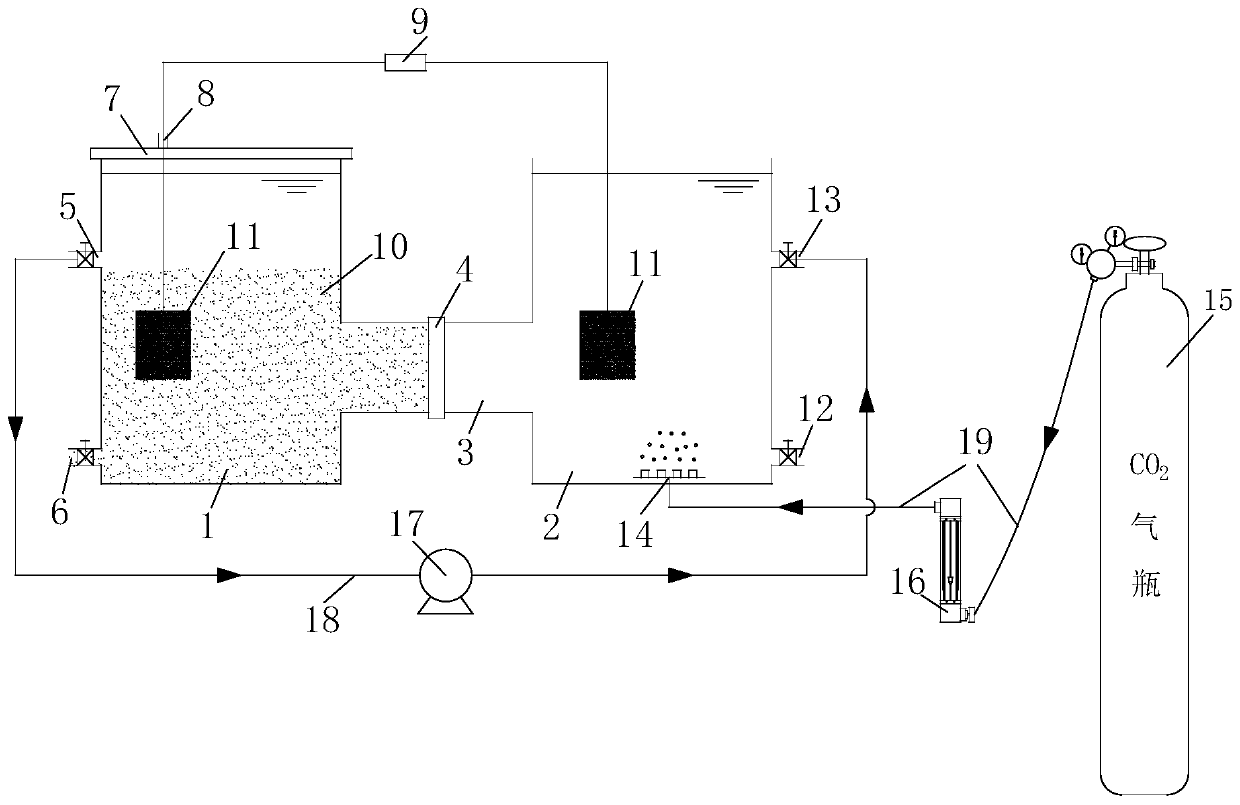
[0027] Such as figure 1 As shown, the present invention proposes a microbial fuel cell, including an anode chamber 1, a cathode chamber 2 and a carbon dioxide ventilation device with a volume of 900 mL. The anode chamber 1 is sealed with a sealing cover 7 to maintain an anaerobic state. The anode chamber 1 is also provided with a water inlet 6, a return port 5 and a wire port 8, and the return port is arranged at the height of the anode chamber. A control valve is installed on the return port, and the anode sludge anaerobic digestion liquid flows back to the cathode chamber 2 through the return liquid hose 18 through the peristaltic pump 17, and the anode chamber 1 and the cathode chamber 2 are connected to the proton exchange membrane 4 in the side pipe 3 Separated, the cathode and anode are connected by wires, the...


PUM


Abstract

The invention belongs to the technical field of microbial fuel cells and water treatment, and provides a microbial fuel cell and a method for promoting wastewater denitrification thereof. The cell comprises an anode chamber, a cathode chamber and a carbon dioxide ventilation device. A sealing cover is arranged on the anode chamber for sealing, and anode sludge anaerobic digestion liquid flows backto the cathode chamber through a peristaltic pump; the anode chamber and the cathode chamber are separated by a proton exchange membrane in a communicating side pipe, the cathode and the anode are connected through a wire, and an external resistor is arranged on the wire; and carbon dioxide is introduced into the cathode through a microporous aeration disc at the bottom of the cathode chamber toserve as a carbon source of the cathode. According to the invention, sludge in the anode chamber of the microbial fuel cell can generate VFA, water and other substances in an anaerobic state, and thereturned anode sludge anaerobic digestion liquid and introduced carbon dioxide are used as a cathode carbon source at the same time, so the sludge of the anode can be reduced, the pH of the cathode can be adjusted, the denitrification efficiency of the cathode can be improved, and the performance of the microbial fuel cell for treating nitrogen-containing wastewater can be improved.

Description

technical field [0001] The invention belongs to the technical field of microbial fuel cells and water treatment, and in particular relates to a microbial fuel cell and a method for promoting denitrification of wastewater thereof. Background technique [0002] MFC (microbial fuel cell) anode is in anaerobic state, microorganisms degrade organic matter to produce electrons, protons, carbon dioxide, VFA and other substances, protons pass into the cathode chamber through the proton exchange membrane, electrons pass into the cathode through the wire, and the sludge in the anode chamber Reduction can be achieved under anaerobic conditions. [0003] The electron donors required for the cathode denitrification process of MFC mainly come from carbon sources and cathode electrons. Different electron donors can affect the denitrification performance of the cathode. There is a certain competition and contradiction between the two electron donors in the MFC cathode system: when the carb...

Claims


Application Information

Patent Timeline
Patent Type & Authority Applications(China)
IPC IPC(8): H01M8/16C02F3/28C02F3/00C02F101/16
CPCC02F3/005C02F3/28C02F2101/163C02F2203/006H01M8/16Y02E60/50
Inventor 李超骆苗苗操家顺许明冯骞方芳郭文薛朝霞罗景阳
Owner HOHAI UNIV
Why Eureka
Try Eureka