Eureka AIR delivers breakthrough ideas for toughest innovation challenges, trusted by R&D personnel around the world.

Air source heat pump heating system capable of cascade heat storage, heat supply and defrosting

An air source heat pump and heating system technology, applied in heating systems, heat storage equipment, household heating, etc., can solve the problems of high-grade electric energy consumption, incomplete functions, low energy utilization rate, etc., and reduce high-grade electric energy. consumption, maximize energy saving and economic benefits, and improve the effect of energy utilization efficiency

Pending Publication Date: 2020-05-12
TIANJIN UNIV
View PDF1 Cites 3 Cited by
  • Summary
  • Abstract
  • Description
  • Claims
  • Application Information

AI Technical Summary

Problems solved by technology

However, the phase change heat storage air source heat pump heating system still has the following problems: 1. The heat pump lacks the defrosting function
[0007] The above-mentioned air source heat pump is coupled with a phase change energy storage device, and most of them only have a single phase change defrosting or phase change heating operation mode, and the functions are not perfect
A few patents can realize phase change defrosting and phase change heating, but in the process of phase change heating, there are too many heat transfer links, and high-grade electric energy is required, and the energy efficiency of the heat pump is low, and the energy saving performance is poor
In addition, most of the above-mentioned patents use a single-stage phase change heat storage device filled with only one phase change material inside, which has poor heat transfer performance and low energy utilization rate

Method used


Image

  • Air source heat pump heating system capable of cascade heat storage, heat supply and defrosting
  • Air source heat pump heating system capable of cascade heat storage, heat supply and defrosting
  • Air source heat pump heating system capable of cascade heat storage, heat supply and defrosting

Examples


Embodiment Construction

[0025]In order to make the purpose, technical solutions and advantages of the embodiments of the present invention clearer, the technical solutions in the embodiments of the present invention will be clearly and completely described below in conjunction with the drawings in the embodiments of the present invention. Obviously, the described embodiments It is a part of embodiments of the present invention, but not all embodiments. Based on the embodiments of the present invention, all other embodiments obtained by persons of ordinary skill in the art without making creative efforts belong to the protection scope of the present invention.

[0026] The present invention will be described in detail below in conjunction with specific embodiments and accompanying drawings.

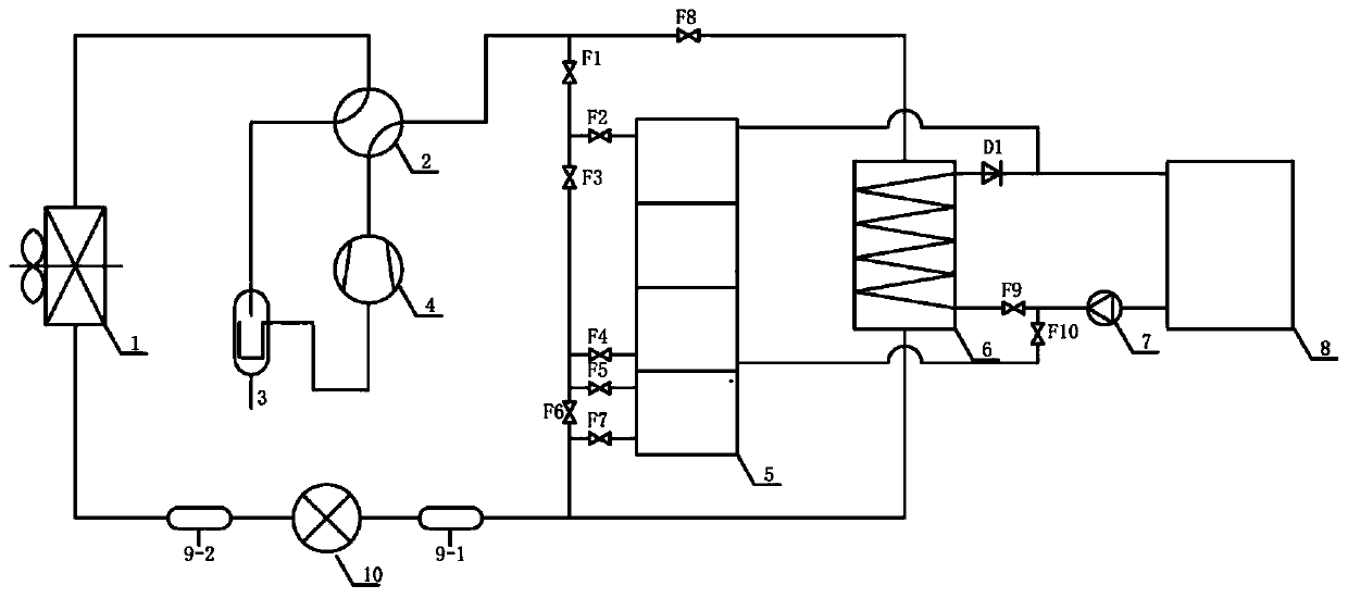
[0027] As shown in the accompanying drawings, an air source heat pump heating system of the present invention capable of cascade heat storage, heat supply and defrosting includes:

[0028] The step phase change ...


PUM


Abstract

The invention discloses an air source heat pump heating system capable of cascade heat storage, heat supply and defrosting. The air source heat pump heating system involves a refrigerant circuit and aheating hot water circuit, wherein the refrigerant circuit involves an evaporator, a four-way reversing valve gas-liquid separator, a compressor, a cascade phase change heat storage device, a condenser, a filter and an expansion valve; and the heating hot water circuit comprises the cascade phase change heat storage device, the condenser, a hot water circulation pump, and a heating end device. According to the air source heat pump heating system, compared with the prior art, stored heat can be directly used for heating, the intermediate link is greatly reduced, and the energy utilization efficiency of the system is improved; the system can achieve six operational mode adjustments according to working conditions, and the economic benefits and the energy-saving benefits are maximized; and the cascade phase change heat storage device provided by the air source heat pump heating system can be divided into a middle-low-temperature heat storage unit for heating and a lower-temperature heatstorage unit for defrosting of a heat pump, so that the cascade utilization of the heat is realized.

Description

technical field [0001] The invention relates to an air source heat pump heating system, in particular to an air source heat pump heating system capable of cascade heat storage, heating and defrosting. Background technique [0002] Air source heat pump is a clean heating method, which has the advantages of energy saving and environmental protection, and is less limited by resource conditions. However, there are still some problems in the application process of air source heat pumps, which limit its further promotion. From a technical point of view, the system operates in a low-temperature and high-humidity environment, and the frosting of the outdoor heat exchanger will reduce the performance of the heat pump and restrict its efficient operation. From an economic point of view, the initial investment of air source heat pumps is higher than that of heating equipment such as electric boilers and gas wall-hung boilers, and the investment recovery period is long, which does not ...

Claims


Application Information

Patent Timeline
Patent Type & Authority Applications(China)
IPC IPC(8): F24D11/02F24D19/10F25B47/02F28D20/02
CPCF24D11/0228F24D19/1039F25B47/02F28D20/02Y02E60/14
Inventor 吕石磊许勃文
Owner TIANJIN UNIV
Why Eureka
Eureka Blog
Learn More