
Dispensing cap with improved tightness

a technology of dispensing orifice and tightness, which is applied in the direction of liquid dispensing, closure lids, closure stoppers, etc., can solve the problems of product leakage, difficult dimensional adjustment, and relatively high amount of force needed to engage the pip in the dispensing orifi

Inactive Publication Date: 2001-07-10
LOREAL SA
View PDF39 Cites 59 Cited by
  • Summary
  • Abstract
  • Description
  • Claims
  • Application Information

AI Technical Summary

Benefits of technology

A second object of the invention is to provide a dispensing cap for which it is easy to adjust the tolerances on the dimensions of the pip and / or of the dispensing orifice and any moulding / demoulding defects of which can be compensated for. It is a further object of the invention to create a particularly well sealed stoppering system, which resists wear throughout the life of the product and operates flexibly, and is easy to open and close. Furthermore, the invention also targets the use of orifices of non-circular cross-section, hitherto unknown in the aforementioned fields of use.
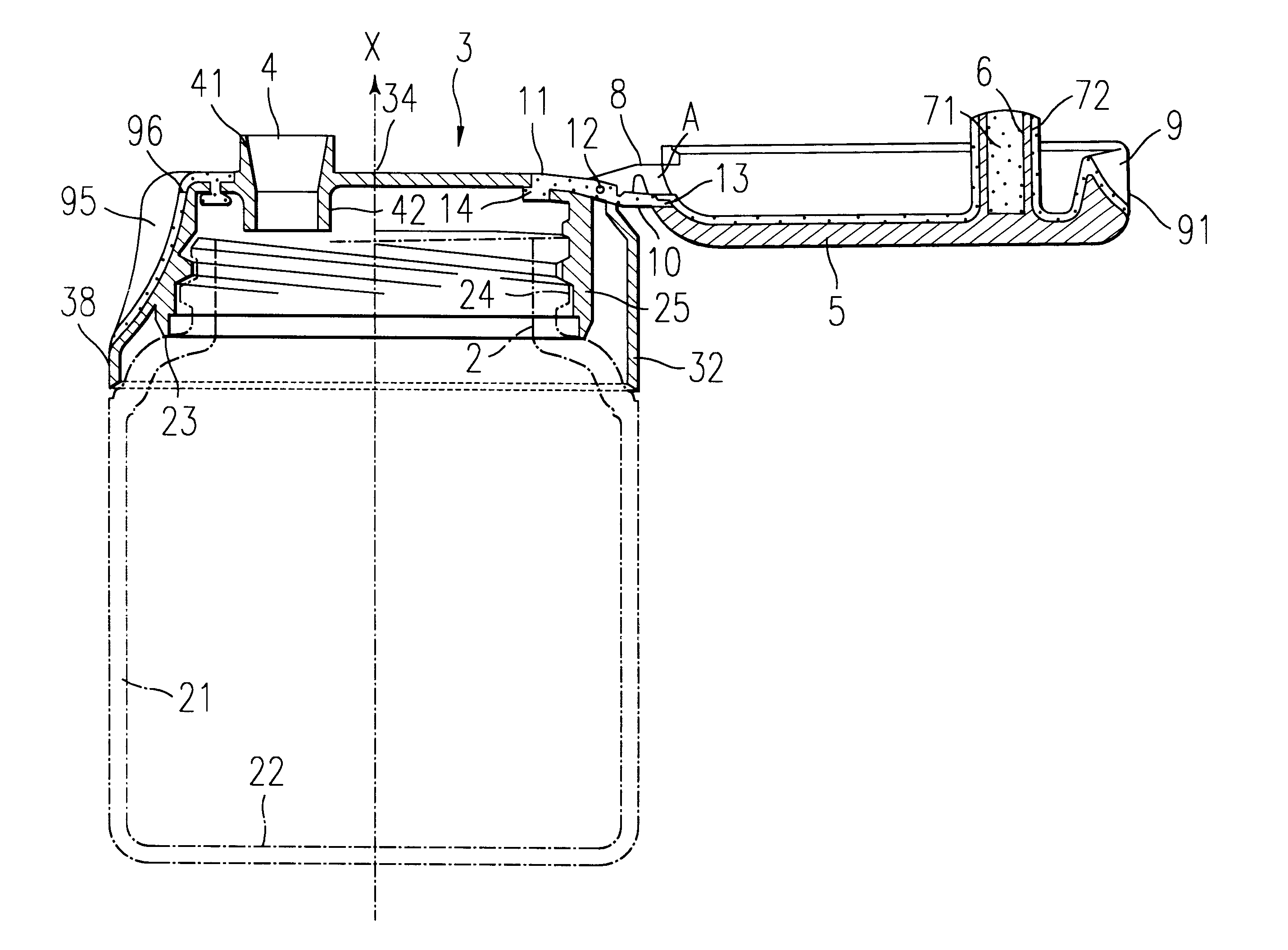
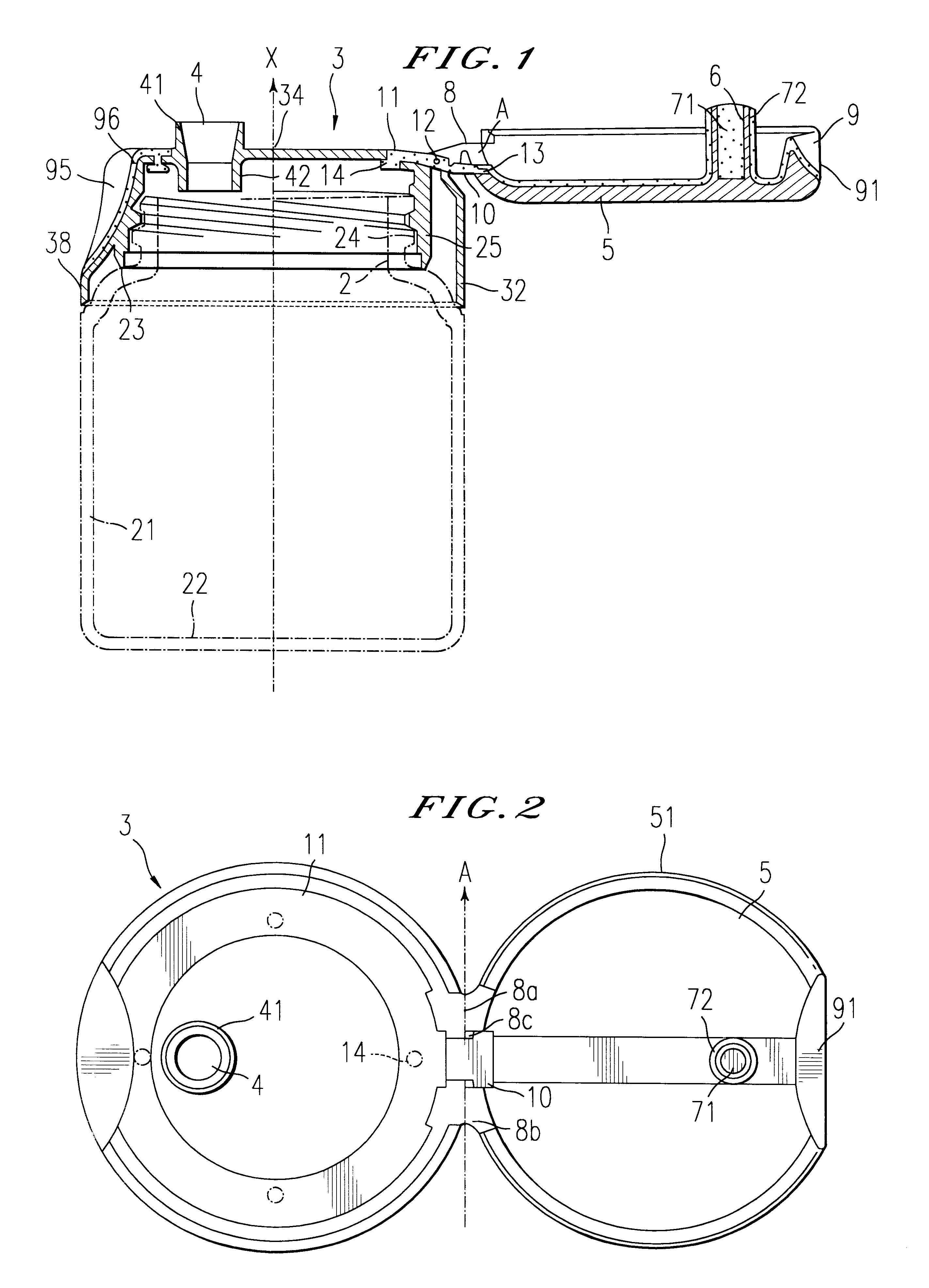
The objects mentioned hereinabove are achieved by depositing a coating of elastomeric material on the outer wall of the pip. Depositing this coating, assuming it is achieved by duplex-injection or by overmoulding onto the pip, is easier to achieve than producing, as in the prior art, a dispensing orifice made in a region made of elastomer. Furthermore, producing a coating on the outer wall of the pip makes it possible, on the one hand, to produce this coating as a thin layer, and therefore make a saving on material, and, on the other hand, to use particularly flexible elastomers (with a hardness of less than 60 Shore A), which makes the cap flexible to use and provides a perfect seal.
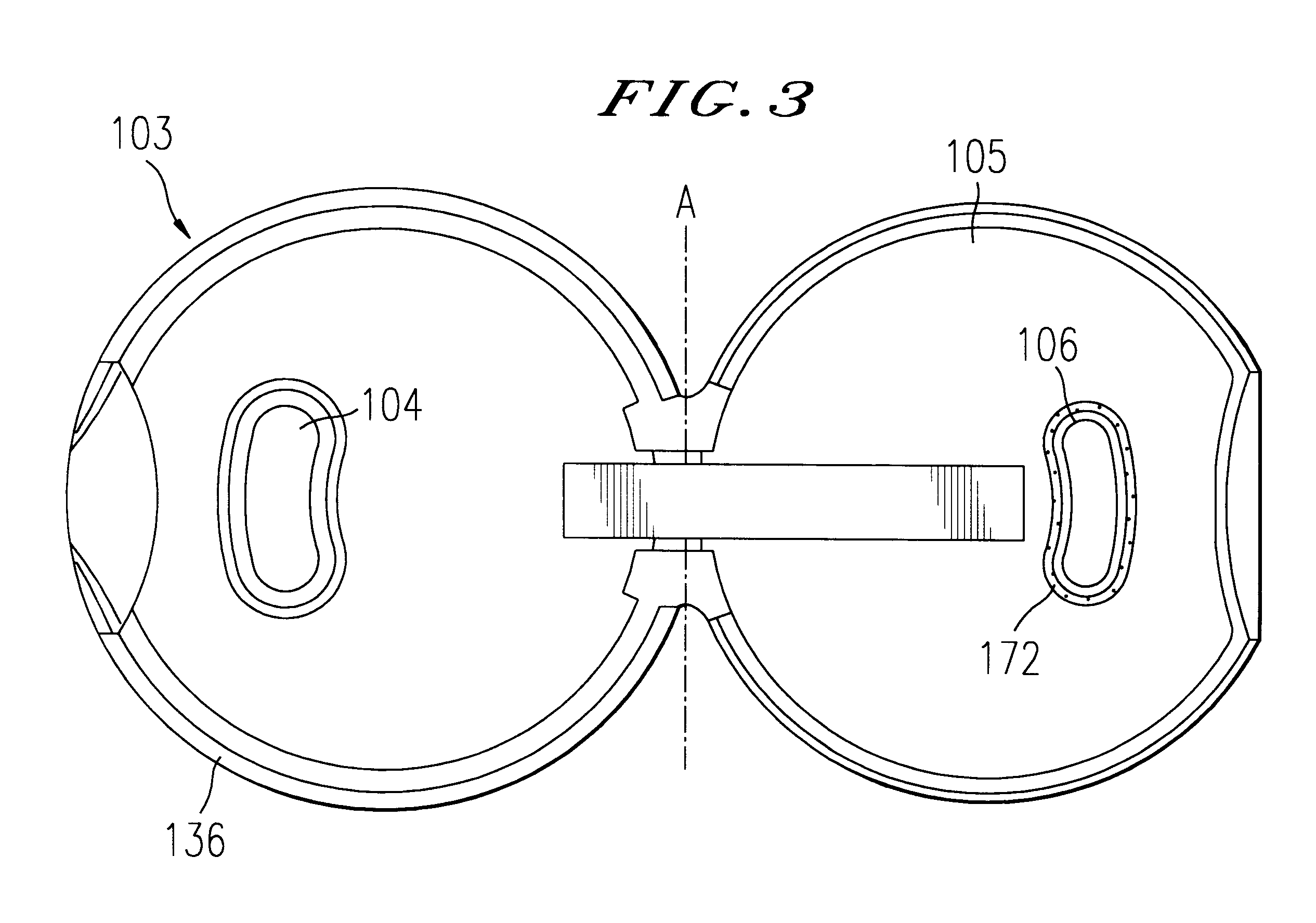
Thanks to the flexibility of the coating, minor defects in the positioning of the pip with respect to the orifice can be compensated for. The same is true, for differences in respective diameters of the orifice and of the pip. In particular, when there is the desire to make orifices of non-circular shape, for example in the shape of a star or flat strip, a good seal can be obtained by arranging a coating of elastomeric material on the external wall of the pip, while at the same time ensuring that the opening and closing of the dispensing orifice will be flexible.
According to another advantageous feature of the invention, it is possible to produce a hollow pip, formed of a cylindrical skirt. In this case, the internal volume of the pip may be filled with flexible material. This is advantageous, because it avoids temporarily trapping residual product inside the pip, which product could run out unintentionally as the lid is opened and dirty the work surface.

Problems solved by technology

Now, with the materials such as polyethylene or polypropylene, commonly used for injection-moulding such caps, dimensional adjustment is very tricky because the tolerances need to remain tighter than 0.05 mm, especially as there is a risk of additional deformation occurring during removal from the mould.
Furthermore, under intense use, and through wear of the pip and / or of the orifice, this pip no longer enters the orifice with friction, and leaks of product can therefore occur.
This cap of the prior art has the drawback that when the lid is closed, a relatively high amount of force is needed to engage the pip in the dispensing orifice.
Although the cap according to U.S. Pat. No. 5,169,035 makes it possible to obtain leaktight stoppering of the dispensing orifice by the pip, it does have the following drawbacks: on the one hand, the annular elastomer component has to be quite thick to allow it to be held in the opening of the cap; and on the other hand, the choice of elastomers that can be used for producing the annular piece is limited.
Furthermore, using such a material, the dimensional tolerances on the pip and the tolerances on positioning it with respect to the dispensing orifice may not be very well met.
Finally, to mount the annular elastomer component in the orifice from inside the cap is a relatively complicated operation requiring special appropriate tooling.

Method used


Image

  • Dispensing cap with improved tightness
  • Dispensing cap with improved tightness
  • Dispensing cap with improved tightness

Examples


Embodiment Construction

With reference to FIG. 1, it is possible to see a dispensing assembly denoted overall by the reference 1, comprising a container 21 having a longitudinal axis X, fitted with a dispensing cap 3 provided with a body referenced 32. The container 21 has a closed bottom 22, and at the opposite end from the bottom, a neck 2 with an external screw thread 24 for attaching the cap body 32 to the container. For this, the cap body has a cylindrical internal skirt 25 with an internal screw thread that complements the screw thread 24 on the neck 2. The container 21 has a circular or oval overall cross-section, this cross section may be any kind, for example polygonal or asymmetric. It is made, for example, of high density polyethylene. The cap body, for its part, is made of a rigid material, such as polypropylene.

The body 32 of the cap 3 has a plateau 34, provided over a portion of its periphery, with a film hinge 8, via which a lid 5 is articulated, allowing this lid to pivot about an axis A co...


PUM

PropertyMeasurementUnit
Thicknessaaaaaaaaaa
Elastomericaaaaaaaaaa
Flexibilityaaaaaaaaaa

Abstract

A dispensing cap which fits on a container containing a fluid product. The cap includes a body provided with a dispensing orifice and a hinged lid which is hinged to the body about an axis. The body and lid are made of a rigid or semi-rigid material. The lid includes a plugging pip for plugging the dispensing orifice when the lid is closed. A coating of elastomeric material is arranged on the outer wall of the pip to produce a seal between the pip and the orifice when the lid is closed.

Description

1. Field of the InventionThe present invention relates to a dispensing cap intended to be fitted to a container containing a fluid product to be dispensed, and to a dispensing assembly equipped with this cap. It is equipped with a stoppering system which can be opened for dispensing the product, and closed for keeping it.2. Discussion of the BackgroundContainers fitted with caps of this kind are customarily used in various fields, for storing and dispensing liquid products, for example in the fields of cosmetics, foodstuffs, household, pharmacy or personal hygiene. These products are, in particular, shampoos, antiseptics, household cleaners, or washing-up products. Thanks to the use of a cap of this kind, on the one hand, it is possible, to prevent the product from spilling out during transport and storage and, on the other hand, the product is protected from dirt from the outside. Furthermore, by using such a cap the user can easily and in a controlled way dispense the product cont...

Claims


Application Information

Patent Timeline
IPC IPC(8): B65D47/08
CPCB65D47/0814
Inventor BAUDIN, GILLES
Owner LOREAL SA
Learn More