


Quick Research
Generate reliable direction feasibility study reports for your R&D in just a few steps.

Technical Q&A
Discover and master advanced knowledge NOW. Basics, ideas, possibilities, all at once.

Find Solutions
As an expert in R&D theories, this can generate solutions to your technical problems instantly.

Evaluate Feasibility
Analyze your overall solution with one click, know your potential R&D risks in advance.

Monitor Landscape
Get weekly tech updates, stay abreast of the latest tech innovations and key insights.
Window mounting structure
A window and structural technology, applied in the direction of building structure, building components, window/door frame, etc., can solve the problem that the average heat transfer coefficient of windows is difficult to reach the heat transfer coefficient, the heat transfer coefficient of external walls and windows is difficult to reduce, and the heat transfer coefficient It is difficult to meet the requirements and other problems, and achieve the effect of reducing the cost, economic significance and sustainable development, and increasing the permeable area
- Summary
- Abstract
- Description
- Claims
- Application Information
AI Technical Summary
Problems solved by technology
Method used
Image


Examples
Embodiment approach 1
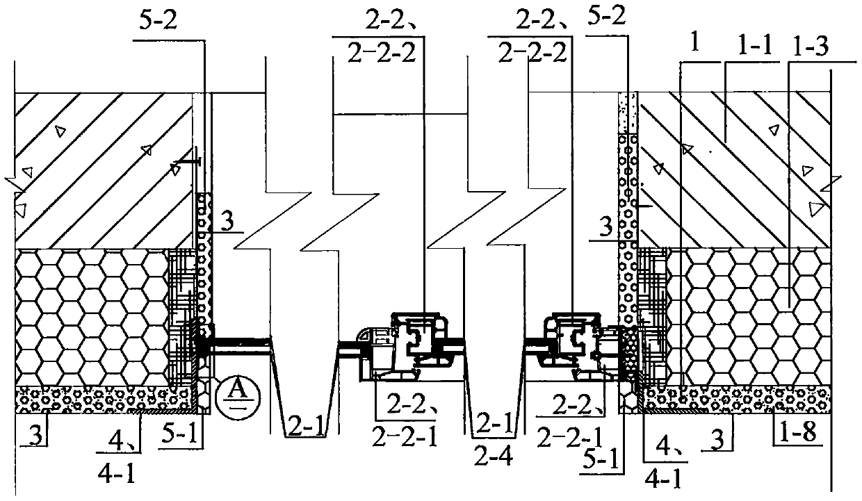
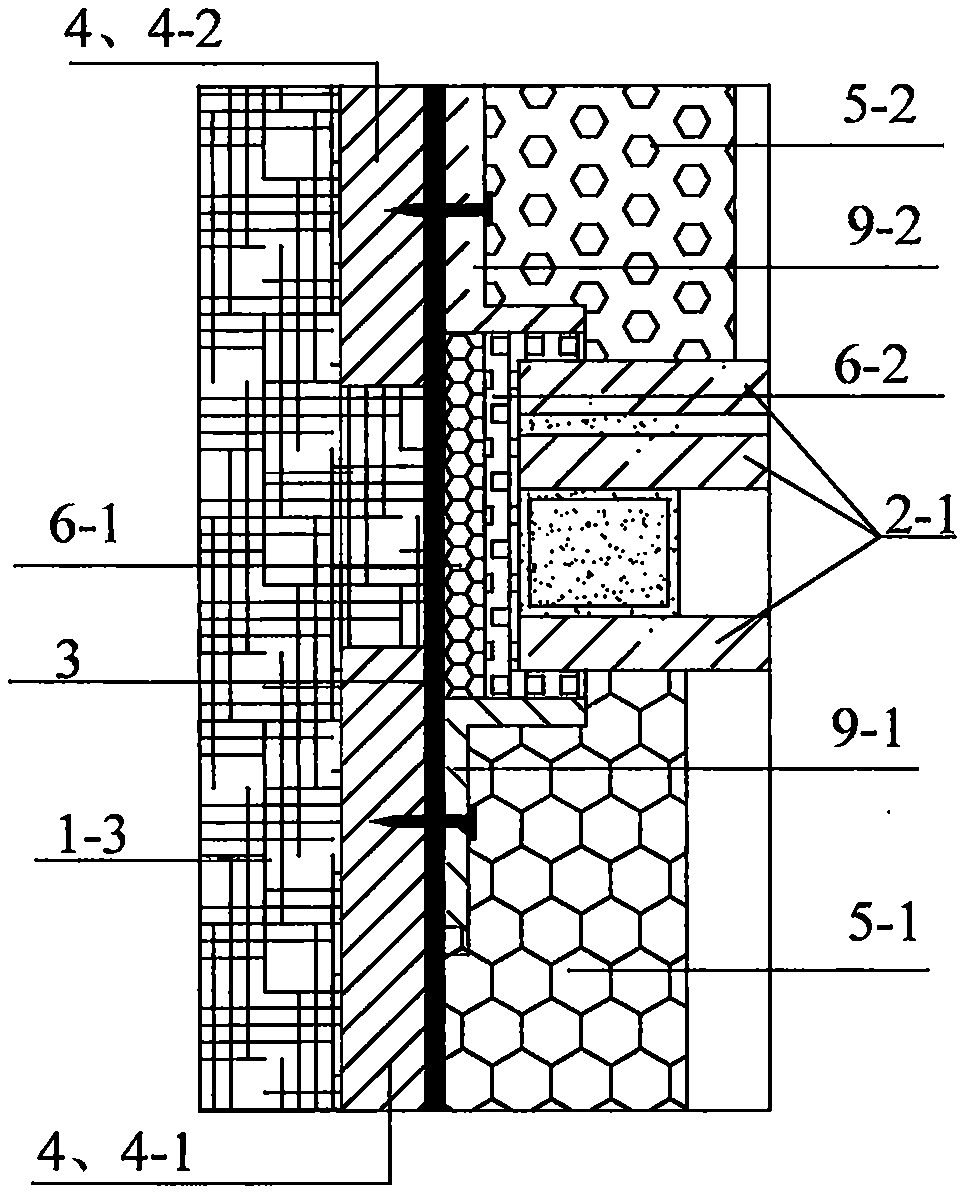
[0029] Implementation mode one: see figure 1 , figure 2 , a kind of window installation structure of the present embodiment, it is made up of exterior wall 1 of building, energy-saving heat-insulating glass 2-1, opening fan 2-2, outdoor damper 9-1, indoor damper 9-2; The sash 2-2 includes a window frame 2-2-1 and a sash 2-2-2; an energy-saving heat insulating glass 2-1 or a non-energy-saving heat insulating glass 2-4 is installed in the sash 2-2-2; A part of the area (left side or right side, upper side or lower side) at the hole is installed with energy-saving heat insulating glass 2-1 without window frame, and the opening fan 2-2 window is installed in another part of the area, and the opening fan 2-2 window is installed according to the actual situation. There is technical installation; when installing the energy-saving heat-insulating glass 2-1 without the window frame, one side of the energy-saving heat-insulating glass 2-1 without the window frame is installed on the m...
Embodiment approach 2
[0033] Implementation mode two: see figure 1 , figure 2 The difference between this embodiment and Embodiment 1 is that this embodiment also adds high-strength and durable fiber cloth 3 and embedded steel plate 4, and embedded steel plate 4 includes outdoor embedded steel plate 4-1 and indoor embedded steel plate 4-2, The embedded steel plate outside the window is the outdoor embedded steel plate 4-1, and the embedded steel plate located inside the window is the indoor embedded steel plate 4-2; the outdoor embedded steel plate 4-1; the outdoor embedded steel plate 4-1 is installed on the wall 1-8 corners of the outer leaf concrete of the body 1, or installed at the 1-8 corners of the plastering protection layer 1-3 of the on-site construction and installation insulation layer, and the indoor pre-embedded steel plate 4-2 is pasted and installed on the insulation layer inside the window room 1-3 or on the indoor side of the wall 1, the outdoor pre-embedded steel plate 4-1 is c...
Embodiment approach 3
[0036] Implementation mode three: see figure 1 , figure 2 , the difference between this embodiment and embodiment one or two is that this embodiment increases the outdoor insulation strip or insulation mortar 5-1, or also increases the indoor insulation strip or insulation mortar 5-2; the outdoor insulation strip or insulation mortar 5 -1 is installed on the outdoor baffle plate 9-1 of the fixed fan 2-1, and is installed on the window side wall on the outside of the opener window frame 2-2-1, or / and the indoor insulation strip or thermal insulation mortar is installed on the fixed fan 2-1 On the window side wall insulation layer 1-3 on the indoor baffle 9-2 or / and on the base wall 1-1, and the window side wall insulation 1 installed on the inside of the opener window frame 2-2-1 - 3 floors or / and 1-1 on the base wall.
[0037] This embodiment can make the thermal resistance of the indoor base wall 1-1 inside the window from the cold spot outside the window not less than the...
PUM
 Abstract
Description
Claims
Application Information
 - R&D Engineer
- R&D Manager
- IP Professional
- Industry Leading Data Capabilities
- Powerful AI technology
- Patent DNA Extraction
Browse by: Latest US Patents, China's latest patents, Technical Efficacy Thesaurus, Application Domain, Technology Topic, Popular Technical Reports.
© 2024 PatSnap. All rights reserved.Legal|Privacy policy|Modern Slavery Act Transparency Statement|Sitemap|About US| Contact US: help@patsnap.com