Eureka AIR delivers breakthrough ideas for toughest innovation challenges, trusted by R&D personnel around the world.

A device for collecting chicken manure

A technology for collecting device and chicken manure, applied in the field of collecting device for chicken manure, can solve the problems of wasting time and manpower, unfavorable use, high odor, etc., and achieve the effect of saving time and manpower, free installation and disassembly, and low hygienic odor.

Active Publication Date: 2021-05-14
湖南友维养殖有限公司
View PDF21 Cites 0 Cited by
  • Summary
  • Abstract
  • Description
  • Claims
  • Application Information

AI Technical Summary

Problems solved by technology

[0002] Chicken manure is a relatively high-quality organic fertilizer, which contains about 1.63%, 1.54%, and 0.85% of pure nitrogen, phosphorus, and potassium. Chicken manure must be fully decomposed before application, and parasites and Its eggs and some infectious bacteria are inactivated through the process of decomposing; the chicken manure produced by general farms is collected manually for loading and transportation. Manual collection is time-consuming and laborious, which increases the labor intensity of workers and wastes time and manpower. The collection is not conducive to cleanliness and hygiene, and the smell is strong. At the same time, when the traditional conveyor belt is used for transportation, the conveyor belt is directly welded to the outside of the collection box, which cannot be installed and disassembled freely, resulting in the user being unable to maintain and clean the conveyor belt, and cannot change the installation position of the conveyor belt. There is no protective device for traditional conveyor belt transportation, and external impacts can easily cause vibration and friction damage between the conveyor belt and the collection box, reducing the working life of the conveyor belt and the collection box; in view of these defects, it is necessary to design a chicken manure collection device

Method used


Image

  • A device for collecting chicken manure
  • A device for collecting chicken manure
  • A device for collecting chicken manure

Examples


Embodiment Construction

[0025] The following will clearly and completely describe the technical solutions in the embodiments of the present invention with reference to the accompanying drawings in the embodiments of the present invention. Obviously, the described embodiments are only some, not all, embodiments of the present invention. Based on the embodiments of the present invention, all other embodiments obtained by persons of ordinary skill in the art without making creative efforts belong to the protection scope of the present invention.

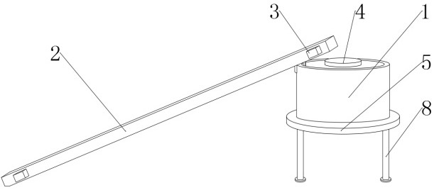
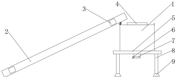
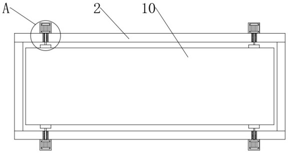
[0026] see Figure 1-6, the present invention provides a technical solution: a chicken manure collection device, including a collection tank 1, a feeding belt housing 2, a motor housing 3, a collection tank cover 4, a support seat 5, a valve 6, a discharge port 7, and a support column 8 , chassis 9, conveyor belt 10, fixed frame 11, rotating motor 12, motor shaft 13, bearing 14, side hole 15, transmission shaft 16, threaded rod 17, first splint 18, sponge pad ...


PUM


Abstract

The invention discloses a chicken manure collecting device, which comprises a collection tank, a feeding belt casing, a motor casing, a collection tank cover, a support seat, a valve, a discharge port, a support column, a chassis, a conveyor belt, a fixed frame, a rotating motor, and a motor shaft , bearing, side hole, transmission shaft, threaded rod, first splint, sponge pad, threaded hole, plastic pad, nut sleeve, second splint, outer anti-slip pad, second top plate and compression spring, the bottom of the collection tank is passed through the screw A support seat is fixed, the bottom of the support seat is located in the center and several support columns are welded on both sides, the top of the collection tank is provided with a collection tank cover, the bottom of the collection tank is provided with a discharge port, and the discharge port is located at At the bottom of the support seat, a valve is set at one end of the outlet. The chicken manure collection device has a simple structure, is easy to operate, and is easy to collect. It does not need manual collection and transportation, saving time and manpower, and it is clean and hygienic. deal with.

Description

technical field [0001] The invention relates to the technical field of chicken manure collection, in particular to a chicken manure collection device. Background technique [0002] Chicken manure is a relatively high-quality organic fertilizer, which contains about 1.63%, 1.54%, and 0.85% of pure nitrogen, phosphorus, and potassium. Chicken manure must be fully decomposed before application, and parasites and Its eggs and some infectious bacteria are inactivated through the process of decomposing; the chicken manure produced by general farms is collected manually for loading and transportation. Manual collection is time-consuming and laborious, which increases the labor intensity of workers and wastes time and manpower. The collection is not conducive to cleanliness and hygiene, and the smell is strong. At the same time, when the traditional conveyor belt is used for transportation, the conveyor belt is directly welded to the outside of the collection box, which cannot be in...

Claims


Application Information

Patent Timeline
Patent Type & Authority Patents(China)
IPC IPC(8): B65G65/32B65G45/10
CPCB65G45/10B65G65/32B65G2201/04
Inventor 邢友维
Owner 湖南友维养殖有限公司
Why Eureka
Eureka Blog
Learn More