An automatic highlight chamfering equipment

A high-gloss chamfering and equipment technology, applied in grinding/polishing equipment, metal processing equipment, grinding drive devices, etc., can solve the problems of low efficiency of grinding and chamfering, high labor intensity of workers, single application, etc., to achieve flexibility and convenience Adjust and locate, easy to promote, widely used effects

Active Publication Date: 2020-12-04
温州拓日工业设计有限公司
View PDF6 Cites 1 Cited by
  • Summary
  • Abstract
  • Description
  • Claims
  • Application Information

AI Technical Summary

Problems solved by technology

[0004] The purpose of the present invention is to provide an automatic high-gloss chamfering equipment to solve the above-mentioned background technology that cannot be well adapted to clamp and fix pipes with different thicknesses, and cannot be used to surround and polish pipes with different diameters. Chamfering, the application is relatively single, the versatility is poor, and it needs to manually push the grinding and cutting mechanism to reciprocate around the pipe mouth, which is laborious, the labor intensity of the workers is high, and the efficiency of grinding and chamfering is low.

Method used


Image

  • An automatic highlight chamfering equipment
  • An automatic highlight chamfering equipment
  • An automatic highlight chamfering equipment

Examples


Embodiment Construction

[0027] The following will clearly and completely describe the technical solutions in the embodiments of the present invention with reference to the accompanying drawings in the embodiments of the present invention. Obviously, the described embodiments are only some, not all, embodiments of the present invention.

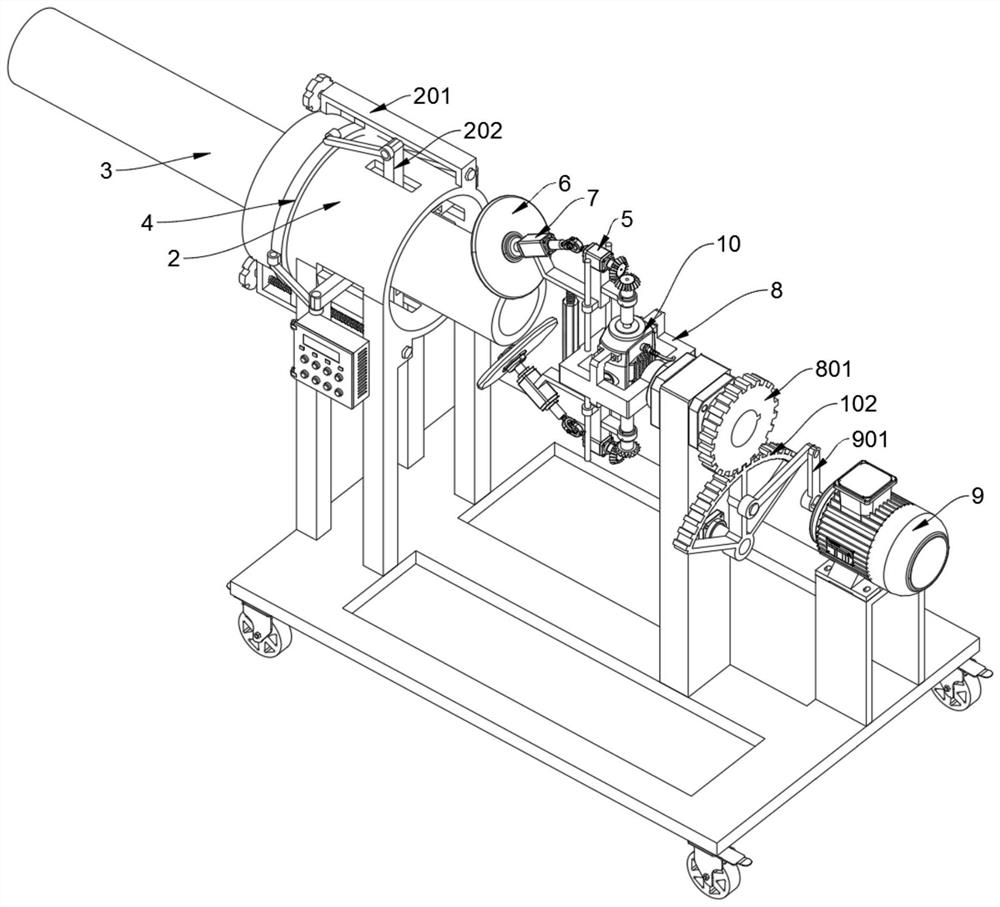
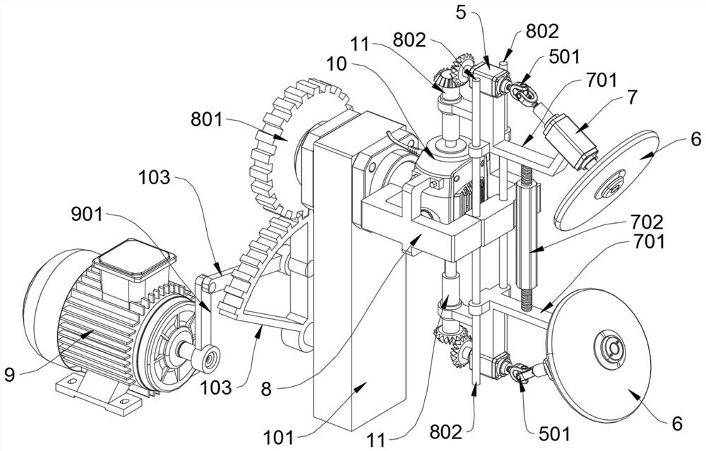
[0028] see Figure 1 to Figure 9 , an embodiment provided by the present invention: an automatic highlight chamfering equipment, including a chassis 1, a bearing mounting column 5, an inclined mounting column 7 and a rotating frame 8, and the chassis 1 includes a mounting brace 101, a sector gear 102 and a connecting rod 103, a swing motor 9 is installed on the rear top position locking support of the chassis 1, and a mounting support plate 101 is welded and fixed at the front middle position of the swing motor 9, and the top middle position of the front side of the chassis 1 is welded and supported With the positioning sleeve 2, the welded pipe 3 is inserted and cla...


PUM


Abstract

The invention discloses an automatic high-gloss chamfering equipment, which relates to the technical field of chamfering equipment, and solves the problem that the existing chamfering equipment needs to manually push the grinding and cutting mechanism to reciprocate around the pipe mouth, which is laborious and labor-intensive for workers. , The problem of low efficiency of grinding chamfering. An automatic high-gloss chamfering equipment, including a chassis and a rotating frame. The chassis includes a mounting support plate, a sector gear and a connecting rod. A swing motor is installed on a locking support at the top position of the rear side of the chassis. The swing motor An installation support plate is welded and fixed at the middle position of the front side of the chassis, and a positioning sleeve is welded and supported at the top of the middle position of the front side of the chassis, and the welded pipe is inserted and clamped in the positioning sleeve; the internal lock of the rotating frame A chamfering motor is tightly inserted, and the double-headed rotating shaft of the chamfering motor is equipped with a drive shaft sleeve in a uniform key connection sleeve. In the present invention, the four pressure blocks can press and clamp the welded pipe to the inside of the positioning sleeve under the swing and push of the push rods at the four places.

Description

technical field [0001] The invention relates to the technical field of chamfering equipment and mechanical processing equipment, in particular to an automatic highlight chamfering equipment. Background technique [0002] Steel pipe refers to a steel material with a hollow section whose length is much greater than the diameter or circumference. According to the cross-sectional shape, it can be divided into circular, square, rectangular and special-shaped steel pipes; according to the material, it can be divided into carbon structural steel pipes, low alloy structural steel pipes, alloy steel pipes and composite steel pipes; Steel pipes for thermal equipment, petrochemical industry, machinery manufacturing, geological drilling, high pressure equipment, etc. [0003] In the on-site welding construction process of water pipelines, it is often necessary to cut and cut the steel pipes with gas cutting according to the length of the pipeline layout. At the cut-off nozzle of the pi...

Claims


Application Information

Patent Timeline
Patent Type & Authority Patents(China)
IPC IPC(8): B24B9/04B24B27/00B24B9/00B24B41/06B24B41/02B24B47/16B24B55/00
CPCB24B9/007B24B9/04B24B27/0007B24B27/0076B24B41/02B24B41/067B24B47/16B24B55/00
Inventor 沈水文
Owner 温州拓日工业设计有限公司
Why Eureka
Try Eureka