Cooling device for mechanical equipment

A technology for cooling devices and mechanical equipment, applied in mechanical equipment, household refrigeration devices, lighting and heating equipment, etc., can solve the problems of reducing equipment service life, low energy utilization, poor heat dissipation efficiency, etc., to improve heat dissipation efficiency , The effect of high energy utilization rate and improved service life

Inactive Publication Date: 2020-11-10
方森杰
View PDF6 Cites 0 Cited by
  • Summary
  • Abstract
  • Description
  • Claims
  • Application Information

AI Technical Summary

Problems solved by technology

[0002] Mechanical equipment is the most widely used equipment in today's production and manufacturing. It is mainly used for processing parts, product manufacturing, etc. Mechanical equipment will always generate corresponding heat during production and operation. If the heat generated before If it is not discharged or absorbed in time, the heat generated during the operation will continue to be superimposed, which is particularly likely to cause wear and tear on the mechanical equipment and reduce the service life of the equipment. The existing cooling device for mechanical equipment has poor heat dissipation efficiency and cooling effect. Not good, the service life is greatly reduced, and the energy utilization rate is not high

Method used


Image

  • Cooling device for mechanical equipment
  • Cooling device for mechanical equipment
  • Cooling device for mechanical equipment

Examples


Embodiment Construction

[0023] The following will clearly and completely describe the technical solutions in the embodiments of the present invention with reference to the accompanying drawings in the embodiments of the present invention. Obviously, the described embodiments are only some, not all, embodiments of the present invention. Based on the embodiments of the present invention, all other embodiments obtained by persons of ordinary skill in the art without making creative efforts belong to the protection scope of the present invention.

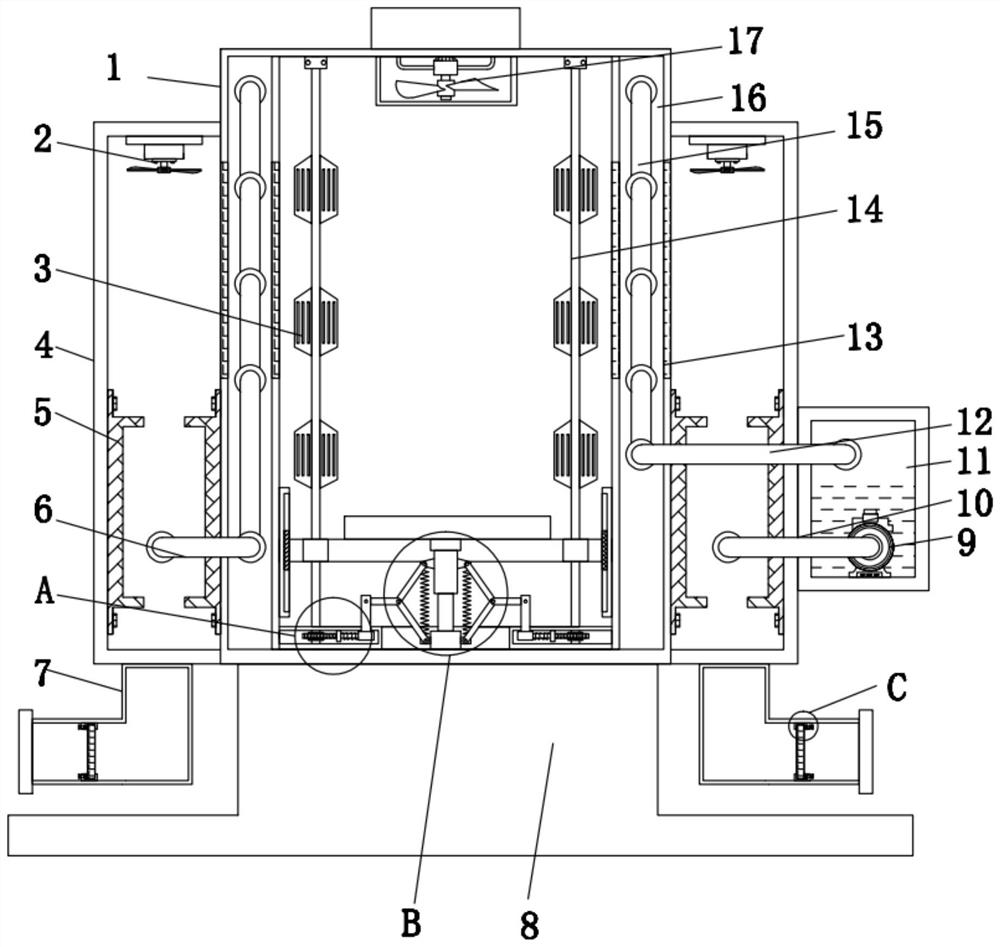
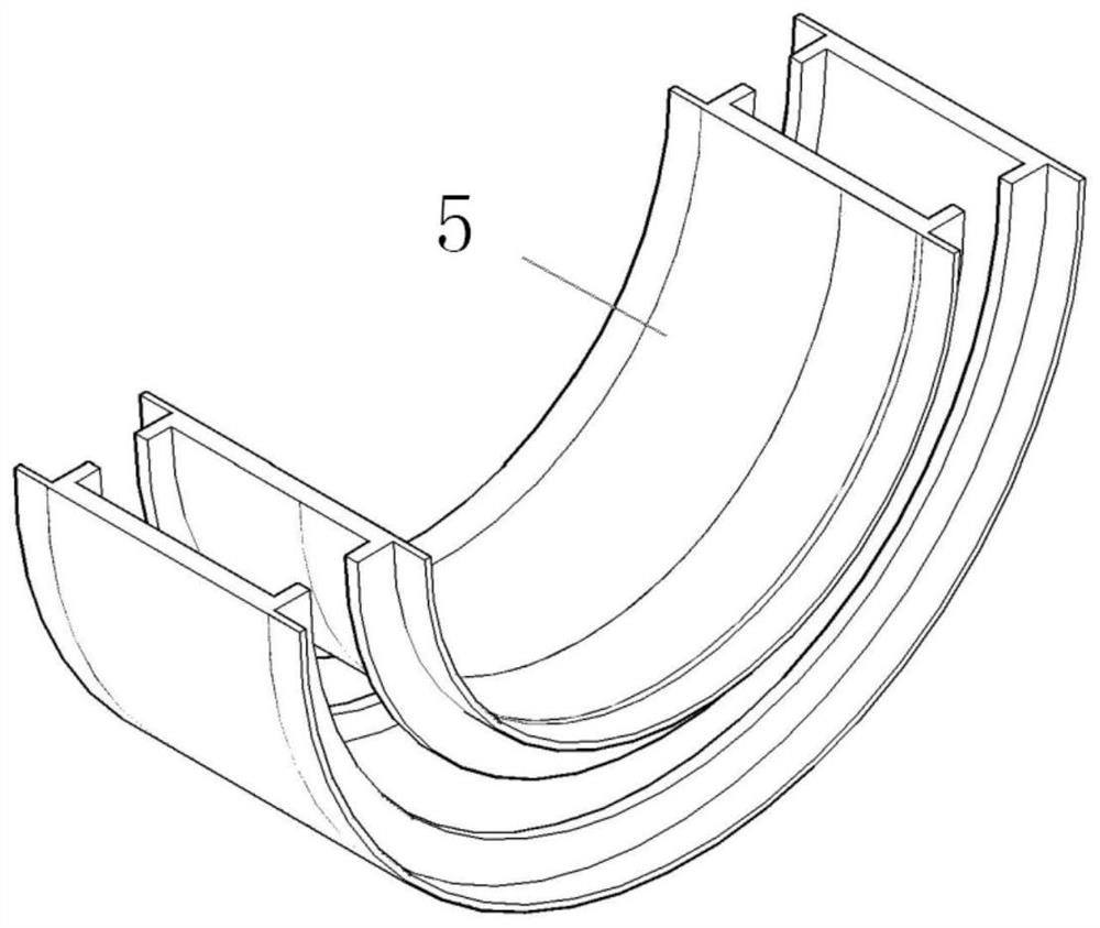
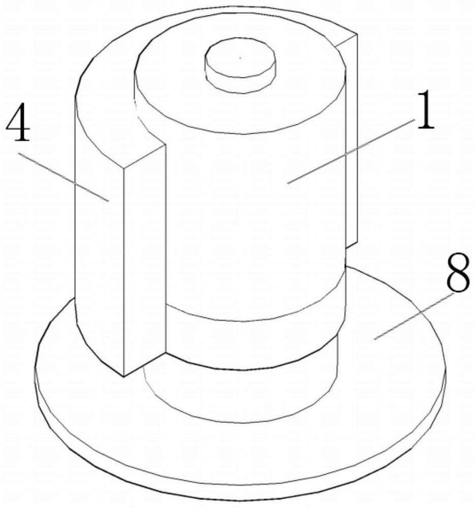
[0024] see Figure 1 to Figure 6 , the present invention provides a technical solution: a cooling device for mechanical equipment, including a body 1, an annular groove 4, an air intake groove 7, a base 8 and a water tank 11, and the top of the base 8 is provided with a body 1;

[0025] The body 1, the annular groove 4 and the base 8 are welded and integrated;

[0026] The structural strength of the device can be improved through the welded integrated structu...


PUM


Abstract

The invention discloses a cooling device for mechanical equipment. The cooling device comprises a body, an annular groove, air inlet grooves, a base and a water tank, wherein the body is arranged at the top of the base, a cavity layer is arranged on the inner side of the body, a condensation pipe is annularly arranged in the cavity layer, the annular groove is formed on the outer side of the body,plate-type condensers are arranged at the lower ends of two sides of the inner wall of the annular groove, the air inlet grooves are oppositely formed in the bottom of the annular groove, the water tank is arranged at the lower end of one side of the annular groove, a water pump is arranged at the bottom in the water tank, and one end of the water outlet pipe extends into the water tank. Throughthe structural design of the plate-type condensers, on one hand, cooled water returns to the interior of the condensation pipe again through the cooling effect of the plate-type condensers to achievecirculating cooling, and on the other hand, when outside air penetrates through the plate-type condensers to enter the interior of the annular groove, cooling in the device can be accelerated, and therefore the heat dissipation efficiency is greatly improved.

Description

technical field [0001] The invention relates to the technical field of mechanical equipment cooling, in particular to a cooling device for mechanical equipment. Background technique [0002] Mechanical equipment is the most widely used equipment in today's production and manufacturing. It is mainly used for processing parts, product manufacturing, etc. Mechanical equipment will always generate corresponding heat during production and operation. If the heat generated before If it is not discharged or absorbed in time, the heat generated during the operation will continue to be superimposed, which is particularly likely to cause wear and tear on the mechanical equipment and reduce the service life of the equipment. The existing cooling device for mechanical equipment has poor heat dissipation efficiency and cooling effect. Not good, the service life is greatly reduced, and the energy utilization rate is not high. Contents of the invention [0003] The object of the present ...

Claims


Application Information

Patent Timeline
Patent Type & Authority Applications(China)
IPC IPC(8): F25D31/00F25D17/02F25D17/06F16F15/067
CPCF16F15/067F25D17/02F25D17/06F25D31/00
Inventor 方森杰
Owner 方森杰
Why Eureka
Try Eureka