Ridge waveguide slot array antenna

A slot array antenna and ridge waveguide technology, applied in leaky waveguide antennas, antennas, antenna arrays and other directions, can solve the problems of electromagnetic wave leakage, high processing cost, poor stability of rectangular waveguides, etc., and achieve low processing costs and strong competitiveness in the market. , good radiation effect

Pending Publication Date: 2020-05-08
SENWELLEN (SHENZHEN) COMM TECH CO LTD
View PDF0 Cites 7 Cited by
  • Summary
  • Abstract
  • Description
  • Claims
  • Application Information

AI Technical Summary

Problems solved by technology

[0004] In the airborne communication and microwave detection system of traditional satellite communication applications, the disadvantages of the slot array antenna are very obvious. For example, although the rectangular waveguide has the characteristics of low loss, it is tightly bonded to multi-layer metal in the millimeter wave application. The requirements for reliability and processing error are too high, and there is electromagnetic wave leakage between metal veneers during assembly
The existing multi-layer metal sheet lamination technology on the market has largely solved the problem of poor stability of the rectangular waveguide, but the processing cost of this multi-layer metal sheet lamination technology is extremely high and is not suitable for mass industrial production

Method used


Image

  • Ridge waveguide slot array antenna
  • Ridge waveguide slot array antenna
  • Ridge waveguide slot array antenna

Examples


Embodiment Construction

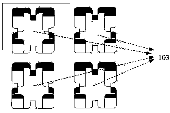
[0040] In order to solve the deficiencies in the prior art, the present invention proposes a ridge waveguide slot array antenna, and uses a cross-shaped high-impedance surface to form an electromagnetic wave suppression structure. The loss of electromagnetic waves can be reduced in the transmission line, and the gain and efficiency of the antenna can be improved.

[0041] Please refer to figure 1 The overall structure diagram of the ridge waveguide slot array antenna. The ridge waveguide slot array antenna is composed of the radiation layer 1, the coupling layer 2 and the feeding layer 3 from top to bottom. The feeding layer 3 adopts the WR-12 standard rectangular waveguide interface vertical The electromagnetic signal is provided, and the full-parallel feeding method is adopted. The electromagnetic wave signal is transmitted to the coupling layer 2 by the five-level T-shaped power divider. The upper surface and the lower surface of the feeding layer 3 are equipped with cross-...


PUM


Abstract

The invention provides a ridge waveguide slot array antenna. The ridge waveguide slot array antenna is composed of a radiation layer, a coupling layer and a feed layer from top to bottom. The feed layer is used for distributing received electromagnetic wave signals and transmitting the electromagnetic wave signals to the coupling layer; the coupling layer performs coupling processing on the electromagnetic wave signals and then transmits the signals to the radiation layer for radiation; the crossed high-impedance surface is arranged on the radiation layer, so that an electromagnetic wave suppression structure is formed, the loss of electromagnetic waves is reduced, the feed layer adopts a ridge gap and waveguide cavity layered processing mode, the processing difficulty is low, vertical feed is carried out through a WR-12 standard rectangular waveguide interface, and the gain and efficiency of the antenna are improved.

Description

technical field [0001] The invention belongs to the field of antennas, in particular to a slot array antenna. Background technique [0002] In the current microwave band, especially the frequency band below 6GHz, the application has tended to be saturated. However, the future-oriented wireless and mobile communication system has higher requirements for the communication rate, such as requiring the download speed to reach 1Gbps, so it can provide higher bandwidth. The millimeter wave band has become a new utilization target, and its frequency range is between 30GHz-300GHz. However, the core obstacle encountered in millimeter wave technology so far is that its oxygen attenuation or water attenuation is relatively serious, and accordingly the distance of millimeter wave communication will be limited, so the development of high-gain antennas has become a millimeter wave communication system technical difficulties in. [0003] Traditional high-gain antennas include reflectors a...

Claims


Application Information

Patent Timeline
IPC IPC(8): H01Q1/38H01Q1/50H01Q13/22H01Q21/06
CPCH01Q1/38H01Q1/50H01Q13/22H01Q21/064
Inventor 刘锦霖何仲夏陈国胜
Owner SENWELLEN (SHENZHEN) COMM TECH CO LTD
Why Eureka
Try Eureka