Engine oil-gas separation device and engine

A separation device, oil and gas separation chamber technology, applied in the direction of engine components, machines/engines, mechanical equipment, etc., can solve problems such as unfavorable condensed lubricating oil backflow, etc., to facilitate the condensation of liquid substances, increase the contact or collision area, and improve quality. effect on efficiency

Active Publication Date: 2020-05-08
CHONGQING LONCIN MOTOR +1
View PDF7 Cites 2 Cited by
  • Summary
  • Abstract
  • Description
  • Claims
  • Application Information

AI Technical Summary

Problems solved by technology

The general design principle of the oil-gas separation labyrinth is to design a labyrinth structure on the discharge path of the oil-gas (lubricating oil and gas) mixture to increase the contact or collision area between the oil-gas mixture and the labyrinth pat...

Method used


Image

  • Engine oil-gas separation device and engine
  • Engine oil-gas separation device and engine
  • Engine oil-gas separation device and engine

Examples


Embodiment Construction

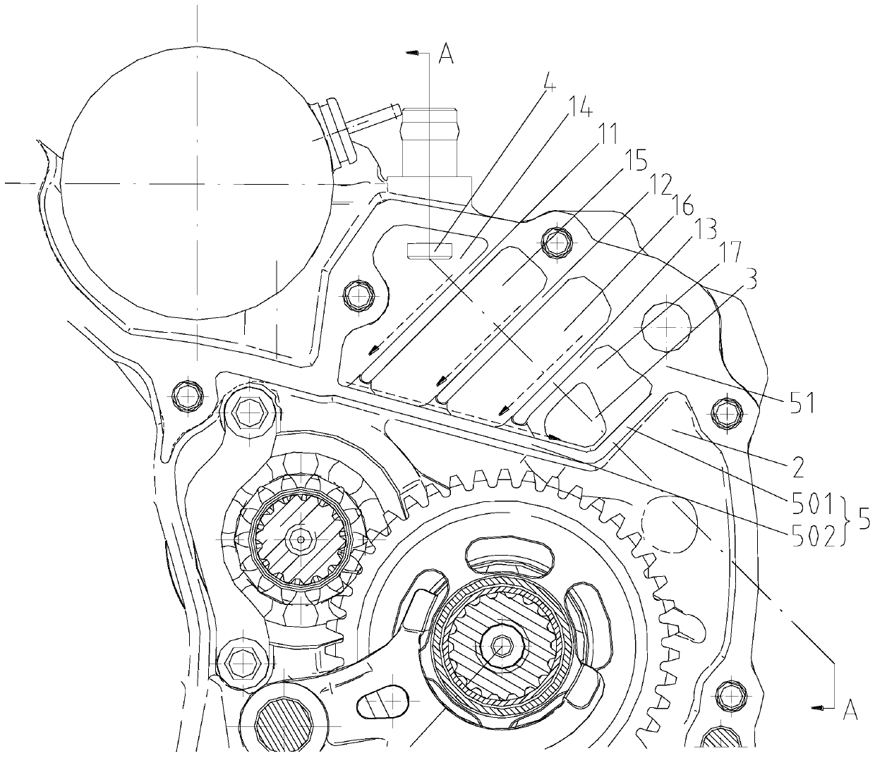
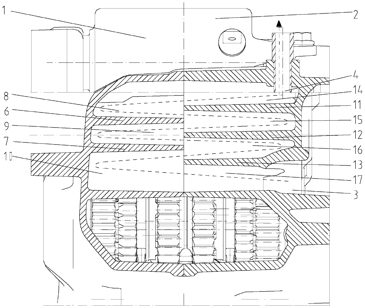
[0019] figure 1 It is a structural schematic diagram of the present invention, figure 2 It is a structural schematic diagram of the A-A direction after the left and right crankcases of the present invention are combined. As shown in the figure: the engine oil-gas separation device and the engine of this embodiment include an isolation plate 5 connected to the crank chamber, and the isolation plate 5 isolates the oil-air separation chamber from the crankcase, and the oil-air separation chamber is set There is a labyrinth channel, and the oil-gas separation chamber is also provided with an air inlet 3 communicated with the inlet end of the labyrinth channel and an exhaust port 4 communicated with the exhaust end of the labyrinth channel, and the air inlet 3 is located in the oil-gas separation chamber bottom. The air inlet 3 is connected to the exhaust port of the crankcase, and the air outlet 4 is connected to the air inlet of the engine air intake system, which is the prior...


PUM


Abstract

The invention discloses an engine oil-gas separation device and an engine. The engine oil-gas separation device comprises an isolation plate connected into a crankshaft chamber, the isolation plate isolates an oil-gas separation chamber from the inside of a crankcase, a labyrinth channel is formed in the oil-gas separation chamber, the oil-gas separation chamber is further provided with a gas inlet communicating with the gas inlet end of the labyrinth channel and a gas outlet communicating with the gas outlet end of the labyrinth channel, and the gas inlet is located in the bottom of the oil-gas separation chamber. According to the engine oil-gas separation device and the engine, the labyrinth channel is arranged so that the contact or collision area of a gas flow path of an oil-gas mixture can be increased, thereby facilitating the condensation of liquid substances; and the gas inlet is a leading-in opening of the oil-gas mixture, and meanwhile is also a backflow opening of the condensed liquid substances after the oil-gas mixture is separated, so that the backflow opening formed in the oil-gas separation chamber is omitted, and the risk that the oil-gas mixture returns to the crankcase through the backflow opening from paths when the oil-gas mixture flows in the oil-gas separation chamber is reduced.

Description

technical field [0001] The invention relates to the field of engines, in particular to an engine oil-gas separation device and an engine. Background technique [0002] Existing two-wheel, three-wheel gasoline engine has following technical shortcoming: piston reciprocating engine, because of the reciprocating motion of piston and a small amount of gas blow-by characteristics at piston place, its crankcase must be designed with engine breathing system (or oil-gas separation system), its purpose Separate the oil-air mixture discharged from the crankcase, let the lubricating oil condense and flow back, and prolong the service life of the lubricating oil. When the engine is working, part of the high-temperature and high-pressure gas leaks into the crankcase through the piston ring. If this part of the gas is not discharged in time, the lubricating oil will become thinner and the performance will deteriorate. After installing the oil-gas separation device, the above-mentioned sub...

Claims


Application Information

Patent Timeline
IPC IPC(8): F01M13/04
CPCF01M13/04F01M2013/0461
Inventor 王良陈志敏周良兵刘智江刘建文
Owner CHONGQING LONCIN MOTOR
Why Eureka
Try Eureka