
Numerical control machine tool

A technology of CNC machine tools and controllers, applied in the field of CNC machine tools, can solve the problems of not having the ability to automatically adjust the level state, etc., and achieve the effects of reliable connection, convenient detection and maintenance, and low cost

Active Publication Date: 2020-05-08
泰州尚诚数控科技有限公司
View PDF8 Cites 4 Cited by
  • Summary
  • Abstract
  • Description
  • Claims
  • Application Information

AI Technical Summary

Problems solved by technology

[0004] The purpose of the present invention is to provide a numerically controlled machine tool to solve the technical problems in the prior art that do not have power recovery for battery power supply, intelligent deceleration and braking, and automatic adjustment of horizontal state.

Method used


Image

  • Numerical control machine tool
  • Numerical control machine tool
  • Numerical control machine tool

Examples


Embodiment Construction

[0031] The present invention is described in detail below in conjunction with accompanying drawing:

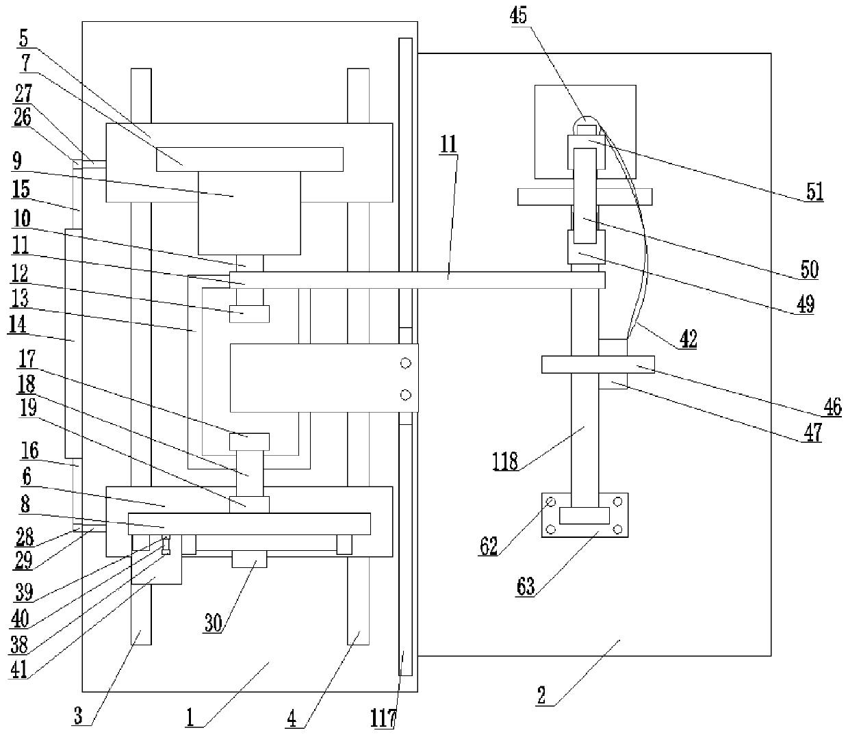
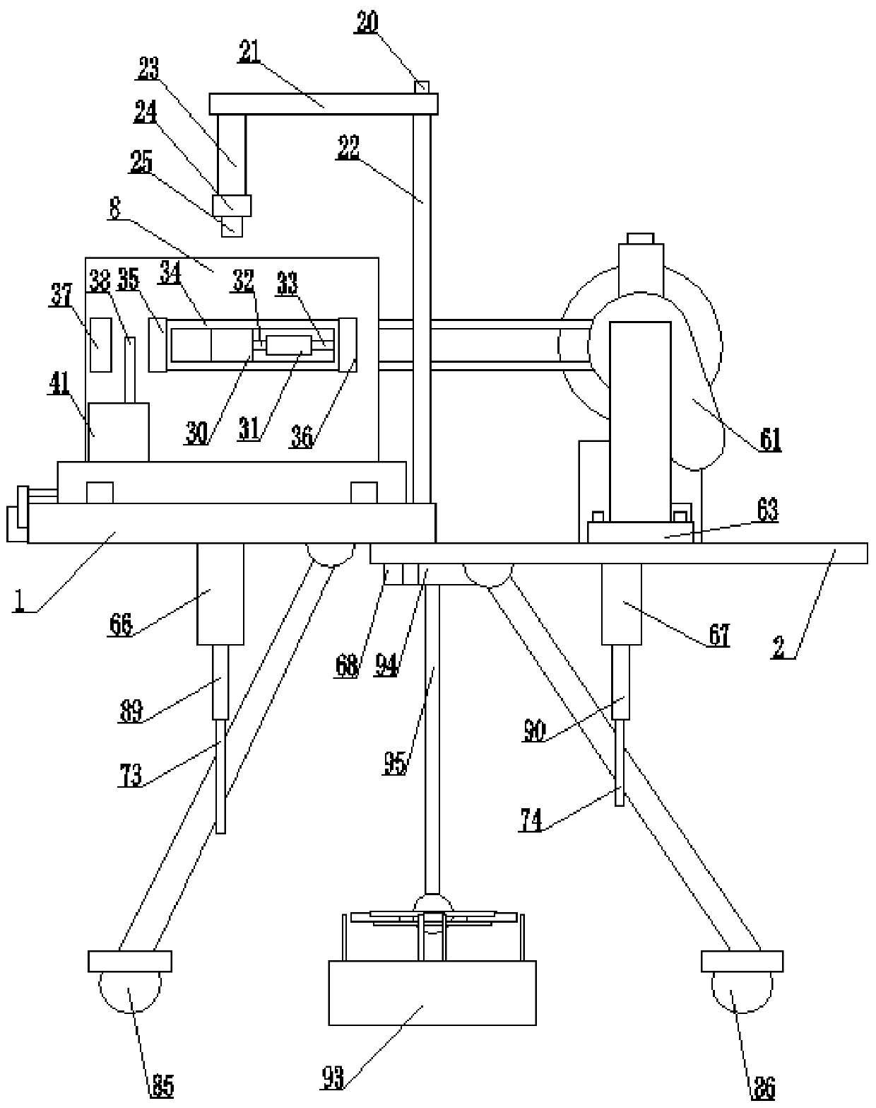
[0032] refer to Figure 1 to Figure 9 , a kind of numerically controlled machine tool provided by the present invention comprises main board 1, sub-board 2, balance control box 93, described main board 1, sub-board 2 are fixedly connected by the third series bolt group 68, the top surface of described main board 1 The left and right sides of the left and right sides are respectively provided with a left guide rail 3 and a right guide rail 4, and the front and rear ends of the left guide rail 3 and the right guide rail 4 are respectively provided with a front movable seat 5 and a rear movable seat 6. The top surfaces of the movable seat 5 and the rear movable seat 6 are respectively provided with a front wall 7 and a rear wall 8, the rear side of the front wall 7 is provided with a motor 9, and the power output end of the motor 9 is provided with a power Shaft 10, the rear end...


PUM


Abstract

The invention provides a numerical control machine tool. A main plate, an auxiliary plate and a balance control box are included. The left side and the right side of the top surface of the main plateare provided with a left guide rail and a right guide rail correspondingly. A front wall and a rear wall are arranged on the top surfaces of a front movable base and a rear movable base correspondingly. A motor is arranged on the rear side face of the front wall, the power output end of the motor is provided with a power shaft, a front chuck is fixed to the rear end portion of the power shaft, a rear chuck is arranged at the front end portion of a connecting column, and the front chuck and the rear chuck are matched to achieve fixing of a to-be-machined workpiece. An upper connecting rod is arranged on the left side of the lower surface of the upper connecting plate, a numerical control tool is connected to the bottom of a tool base, and a collecting chamber for receiving iron scraps generated in the production process is arranged below the numerical control tool. The disclosed technical scheme effectively solves the technical problems that in the prior art, the capability of power recycling for storage battery power supply, intelligent deceleration braking, automatic horizontal state adjusting and the like is not achieved, and popularization and application of the device are facilitated.

Description

technical field [0001] The present invention relates to the technical field of numerical control machine tools, in particular to a numerical control machine tool. Background technique [0002] CNC machine tool is the abbreviation of numerical control machine tool, which is an automatic machine tool equipped with a program control system. The control system can logically process programs with control codes or other symbolic instructions, decode them, express them in coded numbers, and input them into the numerical control device through the information carrier. After arithmetic processing, various control signals are sent by the numerical control device to control the action of the machine tool, and the parts are automatically processed according to the shape and size required by the drawing. [0003] CNC machine tools can better solve the problem of complex, precise, small batch, and multi-variety parts processing. It is a flexible and high-efficiency automatic machine tool...

Claims


Application Information

Patent Timeline
IPC IPC(8): B23Q1/01B23Q1/72B23Q3/12B23Q5/00B23Q11/00B23Q17/00H02J7/32
CPCB23Q1/01B23Q1/72B23Q3/12B23Q5/00B23Q11/00B23Q17/00H02J7/32
Inventor 汪秀英
Owner 泰州尚诚数控科技有限公司
Learn More