
Flow control device and method for improving stability of ventilation cavitation bubbles

A flow control and stability technology, applied in the direction of fluid dynamics/hydrostatics characteristics, transportation and packaging, ships, etc., can solve problems such as collapse and interface instability, so as to enhance the ability to resist disturbance and improve stability Effectiveness and practicality

Pending Publication Date: 2020-05-05
NAT UNIV OF DEFENSE TECH
View PDF0 Cites 6 Cited by
  • Summary
  • Abstract
  • Description
  • Claims
  • Application Information

AI Technical Summary

Problems solved by technology

[0005] At present, most of the existing studies on the stability of the cavitation shape adopt the method of changing the shape of the cavitator and adjusting the ventilation flow rate. Under the action of sudden increase, interface instability or even collapse is easy to occur. How to improve the stability of the supercavitation form of underwater vehicles under complex disturbances is an urgent problem to be solved.

Method used


Image

  • Flow control device and method for improving stability of ventilation cavitation bubbles
  • Flow control device and method for improving stability of ventilation cavitation bubbles
  • Flow control device and method for improving stability of ventilation cavitation bubbles

Examples


Embodiment 1

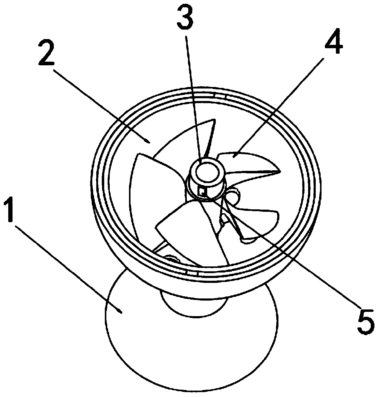
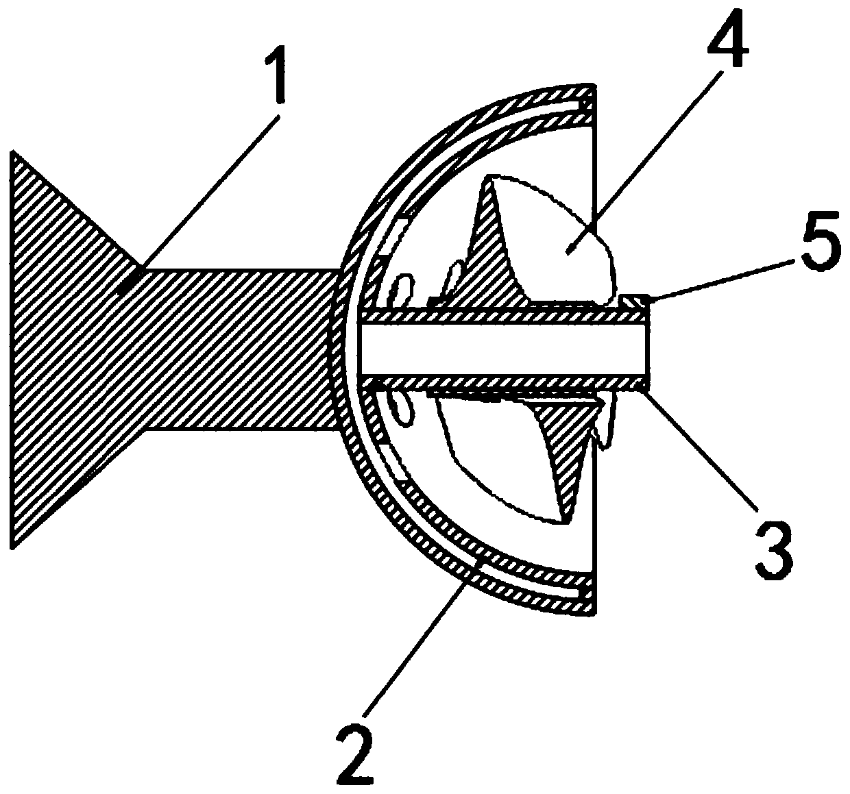
[0046] as attached Figure 1-2 The flow control device shown is used to improve the stability of the ventilated cavitation. Through the cooperation of various components, the gas in the cavitation can be swirled, so as to achieve active control on the shape and stability of the cavitation. It mainly includes interconnected Cavitator 1, air guide bowl 2, ventilation pipeline 3, screw assembly 4, flow controller 5, of which:

[0047] The cavitator 1 is detachably installed on the head of the supercavitating underwater vehicle, which is a conventional cavitator structure, and will not be described in detail here; the present invention makes the cavitator The gas in the bubble is swirled, thereby converting the internal energy of the high-pressure airflow into axial and tangential kinetic energy;

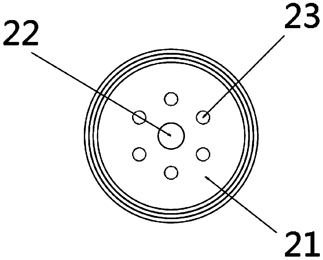
[0048] Air guide bowl 2, if attached Figure 3-4 As shown, it includes a bowl 21 whose end is fixedly connected to the cavitator 1, and the bowl 21 is a double-layer structure with a ...

Embodiment 2

[0056] On the basis of Embodiment 1, the present invention also provides a supercavitating underwater vehicle, which solves the problem of supercavitation shape and underwater vehicle produced during the acceleration process of the traditional underwater vehicle with a fixed structure cavitator. Problems such as mismatched shape, large overall resistance, poor cavitation stability, and poor maneuverability include the main body of the vehicle, the engine, and the flow control device as described in Embodiment 1. The flow control device and the main body of the vehicle are welded, Any one way of screw connection or bonding is fixedly connected, and is arranged coaxially with the tail nozzle of the described engine.

[0057] The supercavitating underwater vehicle described in this embodiment adopts the flow control device described in Embodiment 1, and the ability of the cavitation to resist disturbance can be enhanced by the air flow in the cavitation, and the stability of the c...

Embodiment 3

[0059] On the basis of Embodiment 1, the present invention also provides a flow control method for improving the stability of ventilation cavitation, that is, the use process of the flow control device described in Embodiment 1, including the following steps:

[0060] S1, the flow control device described in Embodiment 1 is fixedly connected to the main body of the navigation body, which can be fixedly connected by welding, threaded connection or bonding;

[0061] S2, during the voyage, if Image 6 As shown, the high-pressure airflow is introduced from the exhaust gas jet of the engine, enters the interlayer 24 through the air inlet 22 along the ventilation pipeline 3 for buffering, and is finally discharged from the exhaust hole 23, under the action of the screw assembly 4 form swirling airflow;

[0062] S3, the high-pressure airflow discharged from the exhaust hole 23 forms an impact on the screw assembly 4 and makes it rotate around the main body of the vehicle;

[0063] ...


PUM


Abstract

The invention discloses a flow control device and method for improving ventilation cavitation stability. The flow control device comprises a cavitator, an air guide bowl, a ventilation pipeline, a spiral assembly, a flow controller and the like. High-pressure airflow enters an interlayer through an air inlet hole along a ventilation pipeline, is finally exhausted from an exhaust hole to form swirling airflow and impacts a spiral assembly to make the spiral assembly rotate around a super air bubble underwater vehicle, the flow controller is additionally arranged on a traditional cavitation device, the air in the cavitation device is made to rotate, internal energy of the high-pressure airflow is converted into axial and tangential kinetic energy, and thereby active control over the cavitation form is achieved. The flow control method for improving stability of the ventilation cavitation bubbles is advantaged in that the generation rate of the ventilation cavitation bubbles can be increased, generation of liquid backflow flow in the cavitation bubbles is inhibited, the cavitation bubbles are rapidly generated till the cavitation bubbles wrap the whole underwater navigation body to form a supercavitation state, and thereby frictional resistance of the surface of the underwater navigation body is greatly reduced.

Description

technical field [0001] The invention relates to the technical field of underwater vehicle supercavitation technology, in particular to a flow control device and method for improving the stability of ventilation cavitation. Background technique [0002] With the continuous advancement of science and technology, it originated from the subversive understanding of cavitation theory. It was previously believed that the cavitation phenomenon of propeller blades would reduce the propulsion efficiency, and the generation of cavitation should be suppressed. Later, it was found that when the underwater vehicle sails at high speed The cavitation phenomenon that appears has shown excellent results in reducing surface frictional resistance, which has attracted widespread attention from researchers at home and abroad. After continuous and in-depth research and study, it has finally developed into artificial ventilation supercavitation technology. The basic principle is By ventilating the ...

Claims


Application Information

Patent Timeline
Patent Type & Authority Applications(China)
IPC IPC(8): B63B1/38
CPCB63B1/38B63B2001/382B63B2001/387Y02T70/10
Inventor 向敏赵小宇张为华郭敏周后村谢泽阳刘波
Owner NAT UNIV OF DEFENSE TECH
Learn More