Eureka AIR delivers breakthrough ideas for toughest innovation challenges, trusted by R&D personnel around the world.

Chilled-mirror dew-point hygrometer capable of quickly measuring extremely low dew point

A dew point meter, extremely low technology, applied in the field of dew point temperature measurement, can solve the problems of inability to reduce the mirror surface temperature to extremely low, the limitation of extremely low dew point measurement, and slow measurement speed, so as to facilitate cleaning and maintenance, and improve the response time. Long, smooth gas flow effect

Inactive Publication Date: 2020-04-21
NO 63837 TROOPS PLA +1
View PDF6 Cites 6 Cited by
  • Summary
  • Abstract
  • Description
  • Claims
  • Application Information

AI Technical Summary

Problems solved by technology

[0003] The chilled mirror dew point meter can meet the needs of most low humidity verification and calibration, and can also be used for precision humidity measurement in the low humidity range. When the water vapor content in the gas is very low, it takes several hours even to form a thin layer of frost layer on the mirror surface, the measurement time is long, and the measurement speed is very slow; secondly, the existing chilled mirror dew point The refrigeration module of the instrument cannot reduce the mirror surface temperature to an extremely low level, which has limitations in the measurement of extremely low dew points;

Method used


Image

  • Chilled-mirror dew-point hygrometer capable of quickly measuring extremely low dew point
  • Chilled-mirror dew-point hygrometer capable of quickly measuring extremely low dew point
  • Chilled-mirror dew-point hygrometer capable of quickly measuring extremely low dew point

Examples


Embodiment Construction

[0030] In order to make the object, technical solution and advantages of the present invention clearer, the present invention will be further described in detail below in conjunction with the accompanying drawings and specific embodiments.

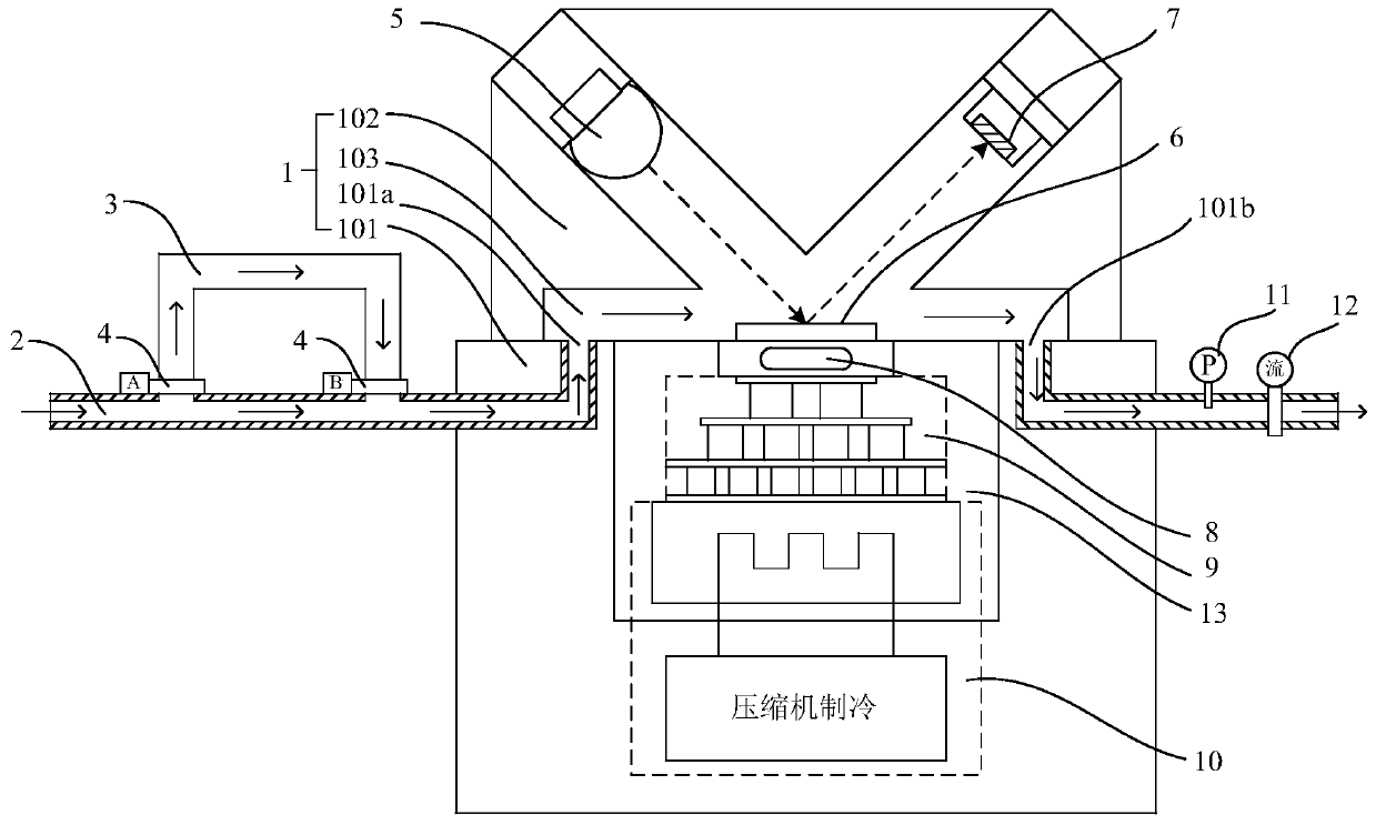
[0031] Please refer to Figure 1 to Figure 5 , the present invention is a chilled mirror dew point meter capable of rapidly measuring extremely low dew points, which includes a gas path system, an optical path system, a refrigeration system and a control system;

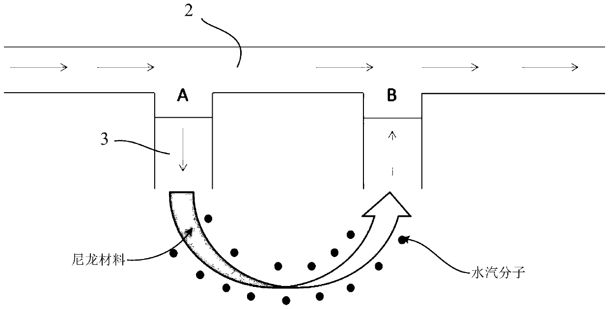
[0032]The gas circuit system includes a test chamber 1, a sampling pipeline 2 and an auxiliary humidification unit. The test chamber 1 includes an air inlet 101a and an air outlet 101b. The sampling pipeline 2 is connected to the air inlet 101a. The side wall of the sampling pipeline 2 is axially There are two openings in sequence. The auxiliary humidification unit includes a humidification pipeline 3 and a solenoid valve 4. Between the opening of the sampling line 2 and the ope...


PUM


Abstract

The invention relates to the field of dew point temperature measurement, and particularly relates to a chilled-mirror dew-point hygrometer capable of quickly measuring an extremely low dew point. Thechilled-mirror dew-point hygrometer comprises a gas path system, a light path system, a refrigerating system and a control system, wherein the gas path system comprises a test cavity, a sampling pipeline and an auxiliary humidifying unit, the auxiliary humidifying unit comprises a humidifying pipeline and an electromagnetic valve, and two ends of the humidifying pipeline are connected to two openings of the sampling pipeline; the light path system comprises a transmitting light source, a mirror surface and a photosensitive receiver, the mirror surface is located in the test cavity, the transmitting light source irradiates the mirror surface, and reflected light is received by the photosensitive receiver; the refrigerating system comprises a semiconductor refrigerator and a compressor refrigerator for performing pre-refrigeration treatment on the semiconductor refrigerator, the cold end of the semiconductor refrigerator is connected to the bottom of the mirror surface, and the hot end of the semiconductor refrigerator is mounted on an evaporator of the compressor refrigerator; and the control system is electrically connected with the gas path system, the light path system and the refrigerating system. The chilled-mirror dew-point hygrometer can measure an extremely low dew point, and is high in measurement speed, high in accuracy and high in stability.

Description

technical field [0001] The invention relates to the field of dew point temperature measurement, in particular to a chilled mirror dew point meter capable of rapidly measuring extremely low dew points. Background technique [0002] As a measurement parameter for evaluating the moisture content in gas, humidity has strict index requirements in many civil and national defense scientific research and production fields. With the development of science and technology, the application field of humidity measurement is continuously expanding, and the requirements are getting higher and higher. For example, various compressed gases are widely used in weapons, aerospace, aviation, nuclear energy, ships, electronics industries, and general assembly, second artillery, navy, air force and other systems. Whether the humidity of the compressed gas is qualified or not affects the normal use of weapons and equipment. . Most of the humidity of compressed gas belongs to the low humidity range....

Claims


Application Information

Patent Timeline
Patent Type & Authority Applications(China)
IPC IPC(8): G01N25/66G01N25/68
CPCG01N25/66G01N25/68
Inventor 宋巍巍顾正华盖文吴亚华韩杰张文清顾光武曾星
Owner NO 63837 TROOPS PLA
Why Eureka
Eureka Blog
Learn More