
Drawing force testing device for sensors and using method thereof

A testing device and pulling force technology, applied in the direction of applying stable tension/pressure to test the strength of materials, instruments, etc., can solve the problems of easily damaged sensors, low production efficiency, affecting sensor test results, etc., to avoid manual operation, The effect of reducing fatigue strength and improving test efficiency

Inactive Publication Date: 2020-04-21
HEFEI SHUSHI IND & TRADE CO LTD
View PDF10 Cites 3 Cited by
  • Summary
  • Abstract
  • Description
  • Claims
  • Application Information

AI Technical Summary

Problems solved by technology

[0003] In the prior art, manual testing is generally used for sensor pullout force testing, which has low production efficiency, and there are relatively large human factors in the test results, which makes the reliability of the test data not high, thus affecting the overall test of the sensor result
[0004] In the process of manual testing, it is not easy to control the manual clamping of the side end of the sensor, and it is easy to damage the sensor. When the manual operation time is long, the fatigue strength of the operator is also increased, resulting in a decrease in efficiency

Method used


Image

  • Drawing force testing device for sensors and using method thereof
  • Drawing force testing device for sensors and using method thereof
  • Drawing force testing device for sensors and using method thereof

Examples


Embodiment Construction

[0039] The following will clearly and completely describe the technical solutions in the embodiments of the present invention with reference to the accompanying drawings in the embodiments of the present invention. Obviously, the described embodiments are only some, not all, embodiments of the present invention. Based on the embodiments of the present invention, all other embodiments obtained by persons of ordinary skill in the art without creative efforts fall within the protection scope of the present invention.

[0040] In describing the present invention, it is to be understood that the terms "opening", "upper", "lower", "thickness", "top", "middle", "length", "inner", "surrounding" etc. Indicating orientation or positional relationship is only for the convenience of describing the present invention and simplifying the description, and does not indicate or imply that the components or elements referred to must have a specific orientation, be constructed and operated in a sp...


PUM


Abstract

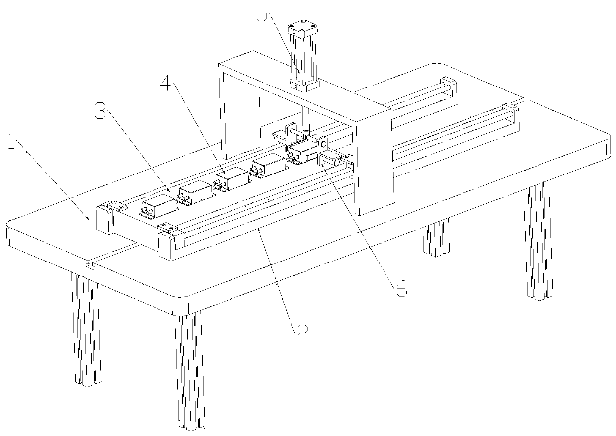
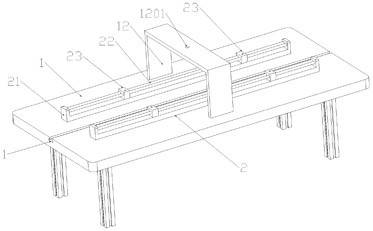
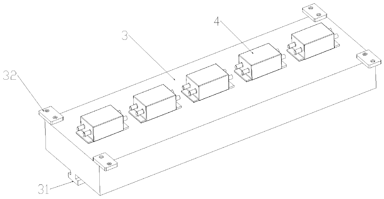
The invention discloses a drawing force testing device for sensors, and a using method of the drawing force testing device. The drawing force testing device comprises a testing workbench, wherein twolinear electric cylinders are fixed to the upper end of the testing workbench, a fixing bottom plate arranged between the linear electric cylinders is arranged at the upper end of the testing workbench, and the sensors are arranged at the upper end of the fixed bottom plate; hydraulic cylinders are arranged at the upper ends of supporting frames, clamping pieces are arranged at the bottom parts ofhydraulic rods, and air cylinders are fixed to the bottom ends of supporting plates. The drawing force testing device drives the air cylinder to clamp and fix the sensors by means of C-shaped clamping plates, the sensors cannot be damaged in the fixing process, the friction force between the rubber pad and the side end portion of each sensor is increased, and the hydraulic cylinder is driven to be lifted upwards by means of the hydraulic cylinder after fixing is firm, thus testing is achieved, and automatic operation is achieved. Meanwhile, the plurality of sensors are fixed on the fixed bottom plate, feeding is carried out through driving of the linear electric cylinders before testing, manual operation is not needed, full-mechanical operation is carried out in the feeding and testing process, the fatigue strength of operators is reduced, and the testing efficiency is improved.

Description

technical field [0001] The invention relates to the field of testing the pull-out force of a sensor, in particular to a pull-out force test device for a sensor and a use method thereof. Background technique [0002] A sensor is a detection element that can sense the measured information and convert the sensed information into electrical signals or other required forms of information output according to certain rules to meet the requirements of information transmission, processing, storage, and display. , recording and control requirements. The sensor is fixed on the circuit board and used as an electrical component in the electrical field. [0003] In the prior art, manual testing is generally used for sensor pullout force testing, which has low production efficiency, and there are relatively large human factors in the test results, which makes the reliability of the test data not high, thus affecting the overall test of the sensor result. [0004] In the process of manua...

Claims


Application Information

Patent Timeline
Patent Type & Authority Applications(China)
IPC IPC(8): G01N3/10G01D18/00
CPCG01N3/10G01D18/00
Inventor 汪泽维黄浩
Owner HEFEI SHUSHI IND & TRADE CO LTD
Learn More