Motor rotors and alternating pole motors

A technology of motor rotor and rotor iron core, applied in the direction of electromechanical devices, electrical components, electric components, etc., can solve the problems of affecting torque output, motor torque decrease, increasing magnetic flux leakage, etc., to increase the magnetic flux area, improve the Effect of output torque and increased magnetic flux area

Active Publication Date: 2022-01-28
GREE ELECTRIC APPLIANCES INC
View PDF18 Cites 0 Cited by
  • Summary
  • Abstract
  • Description
  • Claims
  • Application Information

AI Technical Summary

Problems solved by technology

[0003] In the prior art, the permanent magnets on the alternating pole motor generally adopt a straight or V shape. When the straight shape is used, the permanent magnets are distributed along the outer circumference of the rotor. When the rotor is outer circle, the volume of the permanent magnet should not be too large, the magnetic flux area that the permanent magnet can provide is very small, and it cannot get enough torque; if it is necessary to provide sufficient magnetic flux area, the permanent magnet should be installed near the rotor shaft On the rotor yoke, but it will increase the leakage flux, which also affects the torque output
When the V shape is used, the permanent magnets on the permanent magnet poles are installed in a V-shaped distribution, but because one end of the permanent magnet is close to the rotor shaft, the magnetic flux leakage is increased, causing the motor torque to drop

Method used


Image

  • Motor rotors and alternating pole motors
  • Motor rotors and alternating pole motors
  • Motor rotors and alternating pole motors

Examples


Embodiment Construction

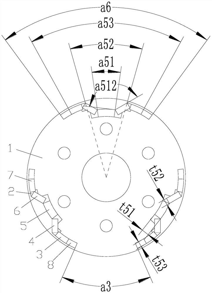
[0027] Combine Figure 1 to 5 As shown, according to the embodiment of the present application, the motor rotor includes a rotor core 1, and the rotor core 1 includes a permanent magnet and alternating electrode, and the permanent magnet is provided, and the migmetric groove 2 is provided. The permanent magnet, the permanent magnet includes the first magnetic segment 3, the second magnetic segment 4, the third magnetic segment 5, the fourth magnetic segment 6, and the fifth magnetic segment 7, and the third magnetic segment 5 is located on the center of the permagnetic pole and along the rotor. The circumferential extension of the core 1, the first magnetic segment 3 and the fifth magnetic segment 7 are located in the radially outer peripheral side of the third magnetic segment 5 and extend along the circumferential direction of the rotor core 1, the second magnetic segment 4 is connected in the first The magnetic segment 3 and the third magnetic segment 5 are connected between the...


PUM


Abstract

The present application provides a motor rotor and an alternating pole motor. The motor rotor includes a rotor core (1), and the rotor core (1) includes permanent magnet poles and alternating poles arranged alternately along the circumferential direction, installation grooves (2) are arranged on the permanent magnet poles, and permanent magnet poles are arranged in the installation grooves (2). The magnet, the permanent magnet comprises the first magnetic segment (3), the second magnetic segment (4), the third magnetic segment (5), the fourth magnetic segment (6) and the fifth magnetic segment (7), the third magnetic segment ( 5) Extending along the circumferential direction of the rotor core (1), the first magnetic segment (3) and the fifth magnetic segment (7) are located on the radially outer peripheral side of the third magnetic segment (5) and along the rotor core (1) The circumferential extension of the second magnetic segment (4) is connected between the first magnetic segment (3) and the third magnetic segment (5), and the fourth magnetic segment (6) is connected between the third magnetic segment (5) and the first magnetic segment Between the five magnetic segments (7). According to the motor rotor of the present application, the flux leakage of the motor can be effectively reduced, the magnetic supply area of ​​the permanent magnet can be increased, and the output torque of the motor can be increased.

Description

Technical field [0001] The present application relates to the technical field of motor equipment, and in particular, there is a motor rotor and an alternate motor. Background technique [0002] The number of permanent magnet synchronous motors used is only half of the number of permanent magnets of the conventional permanent magnet synchronous motor. Therefore, its utilization of permanent magnets is more sufficient, which can significantly reduce the amount of permanent magnets, thereby reducing motor cost. [0003] In the prior art, the permanent magnets on the alternate motor generally use a word type or V3, and when a word type is used, the permanent magnet is distributed along the outer circumference of the rotor, first limited to the outer shape of the rotor, and the permanent magnet is close to When the rotor is round, the volume of the permanent magnet cannot be too large. The magnetic flux area that the permanent magnet can provide is small, and sufficient torque cannot ...

Claims


Application Information

Patent Timeline
Patent Type & Authority Patents(China)
IPC IPC(8): H02K1/276
CPCH02K1/2766H02K2213/03H02K1/2746
Inventor 李权锋陈彬桂鹏千肖勇史进飞
Owner GREE ELECTRIC APPLIANCES INC
Why Eureka
Try Eureka