
Fixed-frequency control method of full-bridge LLC resonant converter

A technology of resonant converter and control method, applied in control/regulation system, conversion of DC power input to DC power output, instruments, etc., can solve the problem of increasing circuit complexity and design cost, increasing control complexity, and complex control circuit and other problems, to achieve the effect of reducing the volume, reducing the circulating current, and simplifying the design process

Active Publication Date: 2020-04-14
HUBEI UNIV OF TECH
View PDF5 Cites 8 Cited by
  • Summary
  • Abstract
  • Description
  • Claims
  • Application Information

AI Technical Summary

Problems solved by technology

The first method adds an auxiliary switching device and uses pulse width modulation (PWM) to adjust the voltage gain, but the added auxiliary power device increases the circuit complexity and design cost, and the additional PWM control increases the complexity of the control
Another method improves the control strategy, but there are disadvantages such as complex control circuit, limited voltage gain, and low efficiency.

Method used


Image

  • Fixed-frequency control method of full-bridge LLC resonant converter
  • Fixed-frequency control method of full-bridge LLC resonant converter
  • Fixed-frequency control method of full-bridge LLC resonant converter

Examples


Embodiment Construction

[0030] The technical solution of the present invention will be described below in conjunction with the accompanying drawings and embodiments, so that those skilled in the art can better understand the present invention.

[0031] Such as figure 1 As shown, the full-bridge LLC resonant converter of the present invention consists of a DC input source V in , Primary side square wave generator Ⅰ, primary side LLC resonant circuit Ⅱ, transformer Ⅲ, secondary side full bridge rectifier circuit Ⅳ, output filter capacitor C o and output resistive load R o constitute. The input voltage of the primary side LLC resonant circuit II is V AB . The components of each component are the first switch tube S on the primary side 1 , the second switch tube S on the primary side 2 , the third switch tube S on the primary side 3 , the fourth switch tube S on the primary side 4 , Resonant capacitance C r , Resonant inductance L r , Exciting inductance L m , Transformer T, secondary first re...


PUM


Abstract

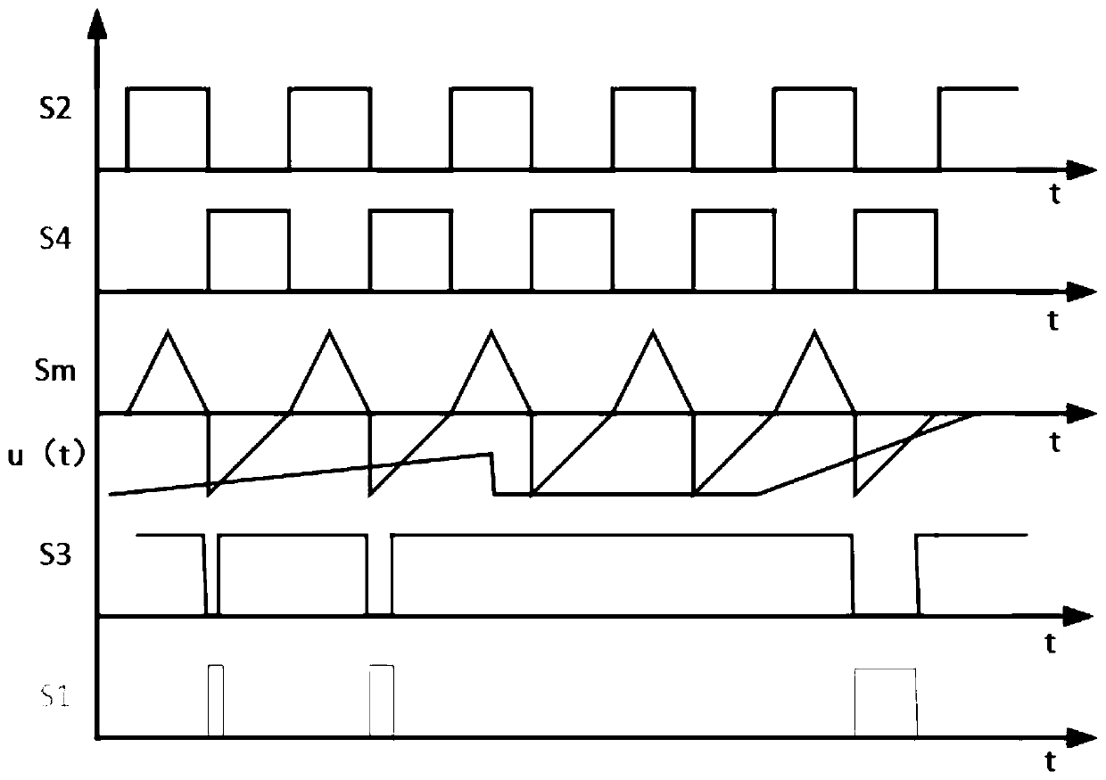
The invention provides a fixed-frequency control method of a full-bridge LLC resonant converter. The full-bridge LLC resonant converter is composed of a direct-current input source Vin, a primary sidesquare-wave generator I, a primary side LLC resonant circuit II, a transformer III, a secondary side full-bridge rectifying circuit IV, an output filter capacitor Co and an output resistance load Ro.The primary side square wave generator I is composed of a primary side first switch tube S1, a primary side second switch tube S2, a primary side third switch tube S3 and a primary side fourth switchtube S4. The primary side LLC resonance circuit II is composed of a resonance capacitor Cr, a resonance inductor Lr and an excitation inductor Lm. The primary side second switch tube S2 and the primary side fourth switch tube S4 are controlled through a pair of fixed-frequency complementary pulses, a duty ratio is 50%, and a switch frequency is equal to a series resonant frequency of the resonantcapacitor Cr and the resonant inductor Lr. Switch pulses of the primary side first switch tube S1 and the primary side third switch tube S3 are controlled through output voltage feedback, and duty ratios of the switch pulses of the primary side first switch tube S1 and the primary side third switch tube S3 are complementary.

Description

technical field [0001] The invention relates to a fixed-frequency control method for a full-bridge LLC resonant converter, especially applied to an isolated DC-DC power converter, and belongs to the technical field of power electronic power converters. Background technique [0002] Isolated DC-DC converters are currently widely used, including data center server power supplies, electric vehicle on-board chargers, photovoltaic DC microgrids, fuel cells, LED drive circuits, etc. The high efficiency and high power density of converters have always been the focus of people the goal that is pursued. The LLC resonant converter has a simple structure and can realize zero voltage switching (ZVS) and zero current switching (ZCS). It has excellent characteristics such as high efficiency, low electromagnetic interference, good voltage regulation performance, and current isolation. It is easy to achieve high efficiency at the resonance frequency Power density has become a research hots...

Claims


Application Information

Patent Timeline
Patent Type & Authority Applications(China)
IPC IPC(8): H02M3/335
CPCH02M3/33569H02M1/0058Y02B70/10
Inventor 潘健刘松林陈庆东陈凤娇吕磊宋豪杰石迪刘雨晴陈光义
Owner HUBEI UNIV OF TECH
Learn More