Pipe compression and shrinkage device for condenser manufacturing and use method of device

A condenser and shrink tube technology, which is applied in the field of condenser processing equipment, can solve the problems of complex disassembly, lower processing efficiency, and long use time, and achieve the effects of reducing waste, improving efficiency, and quickly disassembling and replacing

Pending Publication Date: 2020-04-14
东莞市泰丰空调制冷设备有限公司
View PDF0 Cites 1 Cited by
  • Summary
  • Abstract
  • Description
  • Claims
  • Application Information

AI Technical Summary

Problems solved by technology

[0003] However, the disassembly and assembly of the upper and lower clamping molds on the clamping mechanism of the existing copper tube extrusion tube device used for condenser manufacturing is complicated. When processing copper tubes with different diameters, different upper and lower clamping molds must be replaced It takes a long time to clamp the mold, which reduces the efficiency of processing

Method used


Image

  • Pipe compression and shrinkage device for condenser manufacturing and use method of device
  • Pipe compression and shrinkage device for condenser manufacturing and use method of device
  • Pipe compression and shrinkage device for condenser manufacturing and use method of device

Examples


Embodiment 1

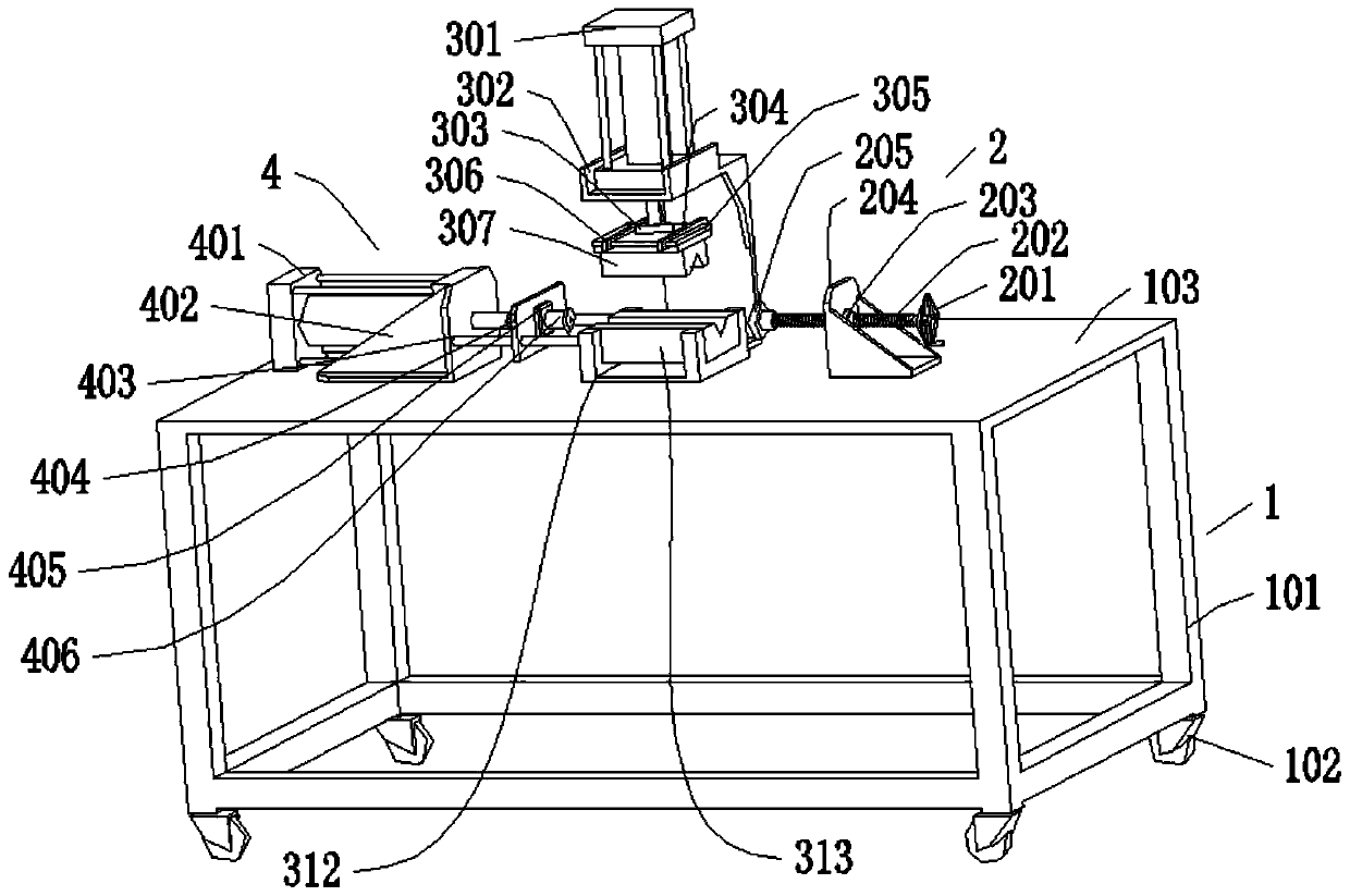
[0043] Such as figure 1 , 3 , 4, and 5, the squeeze tube device used for condenser manufacturing includes a fixing mechanism 1, and an end installed on the upper end of the fixing mechanism 1 for tightening the copper tube to be processed, so as to prevent the copper tube from being processed during the processing process. The clamping mechanism 2 for the sliding of the tube, and the shrinking mechanism 4 for providing power for the shrinking of the copper tube to be processed also include a clamping mechanism 3 for clamping the copper tube to be processed to facilitate the action of the shrinking mechanism 4, wherein , the clamping mechanism 3 , the shrinking mechanism 4 , and the top tightening mechanism 2 are all connected to the fixing mechanism 1 , and the clamping mechanism 3 is connected to the shrinking mechanism 4 .

[0044] The clamping mechanism 3 includes a first oil cylinder 301 and a first fixed frame 302, the first oil cylinder 301 is installed on the upper end...

Embodiment 2

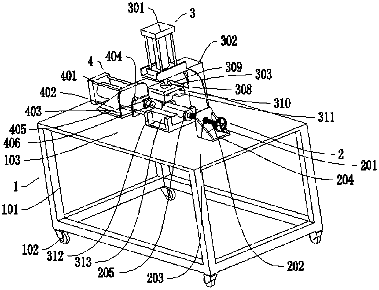
[0046] Such as figure 2 , 3 , 6, and 7, the extruded tube device for condenser manufacturing includes a fixing mechanism 1, and an end installed on the upper end of the fixing mechanism 1 for tightening the copper tube to be processed, so as to prevent the copper tube to be processed from being processed during the processing. The clamping mechanism 2 for the sliding of the tube, and the shrinking mechanism 4 for providing power for the shrinking of the copper tube to be processed also include a clamping mechanism 3 for clamping the copper tube to be processed to facilitate the action of the shrinking mechanism 4, wherein , the clamping mechanism 3 , the shrinking mechanism 4 , and the top tightening mechanism 2 are all connected to the fixing mechanism 1 , and the clamping mechanism 3 is connected to the shrinking mechanism 4 .

[0047] The clamping mechanism 3 includes a first oil cylinder 301 and a first fixed frame 302, the first oil cylinder 301 is installed on the uppe...


PUM


Abstract

The invention discloses a pipe compression and shrinkage device for condenser manufacturing and a use method of the device. The device comprises a fixing mechanism, a jacking mechanism, a pipe shrinkage mechanism and a clamping mechanism; the jacking mechanism is mounted at the upper end of the fixing mechanism and is used for jacking one end of a to-be-machined copper pipe to prevent the to-be-machined copper pipe from sliding in a machining process; the pipe shrinkage mechanism is used for providing power for the to-be-machined copper pipe; the clamping mechanism is used for clamping the to-be-machined copper pipe so that the pipe shrinkage mechanism can act conveniently; the clamping mechanism, the pipe shrinkage mechanism and the jacking mechanism are all connected to the fixing mechanism; and the clamping mechanism is connected to the pipe shrinkage mechanism. According to the pipe compression and shrinkage device for condenser manufacturing and the use method of the device of the invention, a copper pipe for a condenser can be rapidly clamped and fixed through the clamping mechanism; the upper clamping die and lower clamping die of the clamping mechanism can be rapidly disassembled, assembled and replaced, so that copper pipes with different diameters can be machined; and therefore, the waste of non-machining time is reduced, and machining efficiency and the practicability of the device are improved.

Description

technical field [0001] The invention relates to the technical field of condenser processing equipment, in particular to a squeeze tube device for condenser manufacture and a use method thereof. Background technique [0002] The pipe shrinking machine is a hydraulic automatic pipe end processing machine that expands and shrinks the end face of the pipe fittings under normal conditions. It is controlled by an integrated control touch display screen. The pipe fittings can be expanded, shrunk, bulged, and upset by changing the mold. Ribs and other pipe ends can be processed and formed, and manual, inching or automatic processing can be freely decided according to user needs. It is composed of mold, axial positioning oil cylinder, axial positioning angle iron and other main parts. [0003] However, the disassembly and assembly of the upper and lower clamping dies on the clamping mechanism of the existing copper tube extrusion tube device used for condenser manufacturing is compl...

Claims


Application Information

Patent Timeline
Patent Type & Authority Applications(China)
IPC IPC(8): B21D41/04B21D43/00B21D53/06
CPCB21D41/04B21D43/003B21D53/06
Inventor 杨萍
Owner 东莞市泰丰空调制冷设备有限公司
Why Eureka
Try Eureka