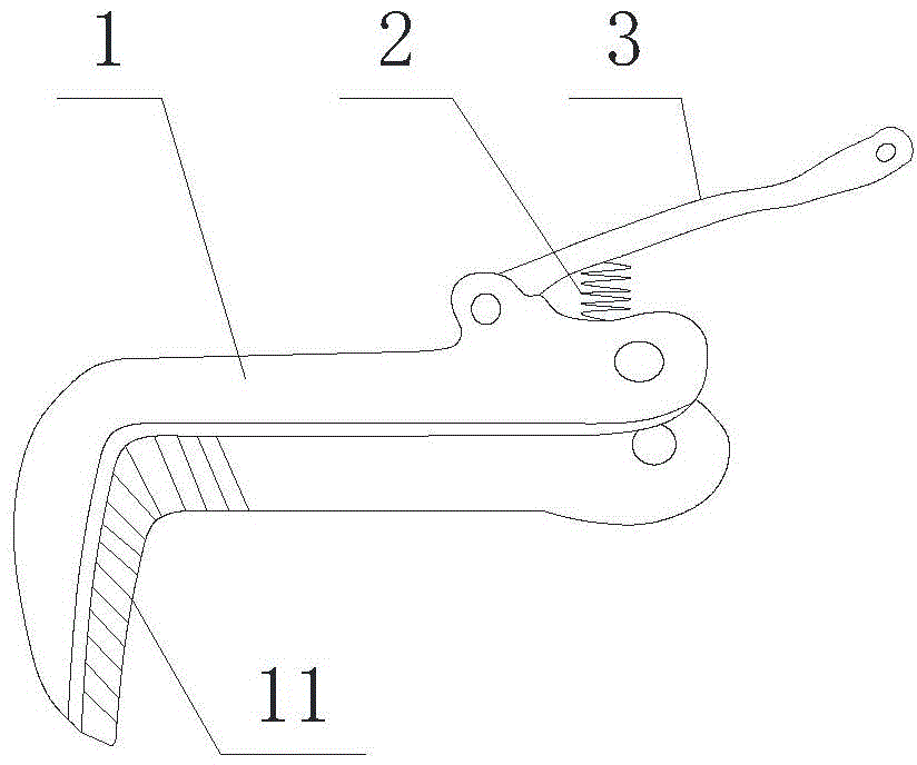
Double-adjusting rapid and convenient spanner
A double-adjustment and fast technology, applied in the direction of wrenches, screwdrivers, manufacturing tools, etc., can solve the problems of cumbersome operation process, inconvenient, single adjustment method, etc., and achieve the effect of quick adjustment, simple structure and improved friction
- Summary
- Abstract
- Description
- Claims
- Application Information
AI Technical Summary
Problems solved by technology
Method used
Image
Examples
Embodiment 1
[0041] Such as Figure 1 to Figure 5 As shown, a kind of double-adjustment quick and convenient wrench of the present embodiment 1 comprises:
[0042] A handle bar 5 with an external thread is provided, and the front end of the handle bar 5 is bent downward to form a second clamping portion 51; the middle part of the handle bar 5 is provided with a sliding hole 52;
[0043] A spiral ring 6 threadedly matched with the handle rod 5; the spiral ring 6 can slide forward and backward along the handle rod 5 through rotation;
[0044] A movable rod 1, the front end of the movable rod 1 is bent downward to form a first clamping portion 11, and the lower bottom surface of the rear end of the movable rod 1 is upwardly provided with a groove for accommodating the handle rod 5;
[0045] The forward and backward movement of the coil 6 is transmitted to the linkage 4 of the movable rod 1 .
[0046] The linkage 4 is specifically: a first clamping shaft 41 and a second clamping shaft 43 are...
Embodiment 2
[0050] Such as Image 6 As shown, a kind of double adjustment quick and convenient wrench of the present embodiment 2 comprises:
[0051] A handle bar 5 with an external thread is provided, and the front end of the handle bar 5 is bent downward to form a second clamping portion 51;
[0052]A spiral ring 6 threadedly matched with the handle rod 5; the spiral ring 6 can slide forward and backward along the handle rod 5 through rotation;
[0053] A movable rod 1, the front end of the movable rod 1 is bent downward to form a first clamping portion 11, and the lower bottom surface of the rear end of the movable rod 1 is upwardly provided with a groove for accommodating the handle rod 5;
[0054] The linkage piece that transmits the forward and backward movement of the coil 6 to the movable rod 1 .
[0055] Described linkage is specifically: the hand-held bar 5 on both sides front and back of described spiral ring 6 is respectively provided with the barrier plate one 71 and the ba...
Embodiment 3
[0058] Such as Figure 7 ~ Figure 10 As shown, a kind of double-adjustment quick and convenient wrench of the present embodiment 3 comprises:
[0059] A handle bar 5 with an external thread is provided, and the front end of the handle bar 5 is bent downward to form a second clamping portion 51;
[0060] A spiral ring 6 threadedly matched with the handle rod 5; the spiral ring 6 can slide forward and backward along the handle rod 5 through rotation;
[0061] A movable rod 1, the front end of the movable rod 1 is bent downward to form a first clamping portion 11, and the lower bottom surface of the rear end of the movable rod 1 is upwardly provided with a groove for accommodating the handle rod 5;
[0062] Transmit the forward and backward movement of the coil 6 to the linkage part 2 8 of the movable rod 1 .
[0063] The linkage part 2 8 is specifically as follows: the two sides of the middle part of the handle bar 5 are respectively provided with slideway grooves 53; the slid...
PUM
 Abstract
Description
Claims
Application Information
 - R&D
- Intellectual Property
- Life Sciences
- Materials
- Tech Scout
- Unparalleled Data Quality
- Higher Quality Content
- 60% Fewer Hallucinations
Browse by: Latest US Patents, China's latest patents, Technical Efficacy Thesaurus, Application Domain, Technology Topic, Popular Technical Reports.
© 2025 PatSnap. All rights reserved.Legal|Privacy policy|Modern Slavery Act Transparency Statement|Sitemap|About US| Contact US: help@patsnap.com


