
Light cone sensor for partial discharge measurement

A partial discharge and sensor technology, applied in the field of light cone sensors, can solve the problems of inability to reflect discharge characteristics intrinsically, limited sensitivity and viewing angle range, and low sensitivity, so as to improve the quality of operation and maintenance and state detection, shorten the discovery time, The effect of high sensitivity

Inactive Publication Date: 2020-04-10
YUNNAN POWER GRID CO LTD LINCANG POWER SUPPLY BUREAU
View PDF7 Cites 4 Cited by
  • Summary
  • Abstract
  • Description
  • Claims
  • Application Information

AI Technical Summary

Problems solved by technology

The currently proposed optical detection methods that can be used for partial discharge of equipment insulation mainly include fluorescent optical fiber detection and acousto-optic detection. The former is to put fluorescent optical fiber into the equipment to collect the optical signal of discharge, and then guide it to the outside for photoelectric conversion and signal. The processing system is connected, this method is restricted by the limited light-receiving area of ​​the optical fiber, and the sensitivity is low; the latter uses the principle of acousto-optic interference to convert the acoustic signal caused by the discharge into an optical interference signal, and its optical signal cannot intrinsically reflect the discharge characteristics
Overall, although current optical partial discharge measurement sensors can limit non-optical interferences, their sensitivity and viewing angle range are limited, and they are not widely used in practical devices

Method used


Image

  • Light cone sensor for partial discharge measurement
  • Light cone sensor for partial discharge measurement
  • Light cone sensor for partial discharge measurement

Examples


Embodiment Construction

[0020] The following will clearly and completely describe the technical solutions in the embodiments of the present invention with reference to the accompanying drawings in the embodiments of the present invention. Obviously, the described embodiments are only some of the embodiments of the present invention, not all of them. Based on the embodiments of the present invention, all other embodiments obtained by persons of ordinary skill in the art without making creative efforts belong to the protection scope of the present invention. In the following description, in order to clearly show the structure and working method of the present invention, the accompanying drawings will be used as the basis to describe with the help of many directional words, but "front", "rear", "left", "right", Words such as "up" and "down" are to be understood as convenient terms, and should not be understood as restrictive terms.

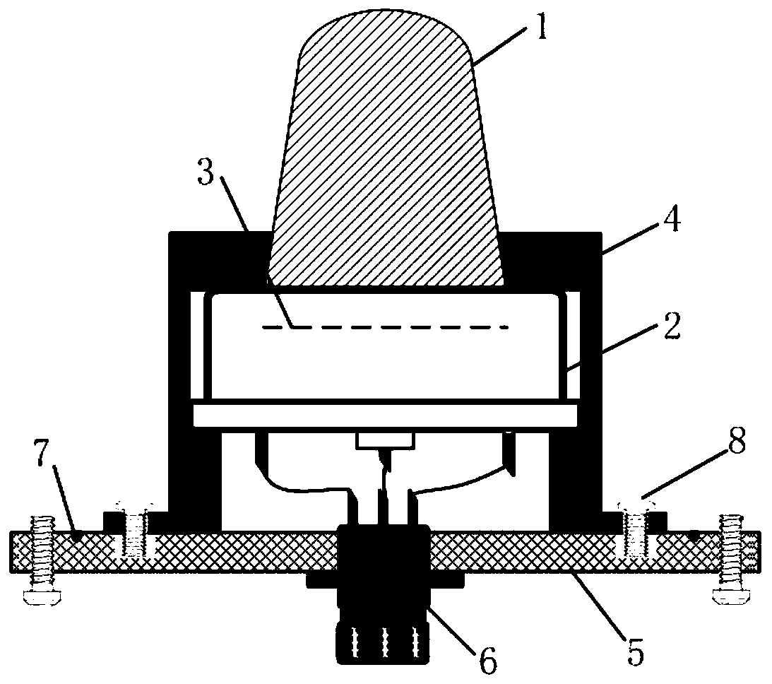
[0021] Figure 1-4 The light cone sensor shown is based on the partia...


PUM

PropertyMeasurementUnit
diameteraaaaaaaaaa
Sensitivityaaaaaaaaaa
transmittivityaaaaaaaaaa

Abstract

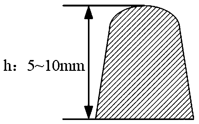
The invention discloses a light cone sensor based on partial discharge measurement, and aims to provide a light cone sensor based on partial discharge measurement with high sensitivity. The light conesensor comprises a photon collection probe, a fixed shell, a silicon photodiode, a sealing flange plate and an aviation plug. The multi-core aviation plug is fixedly arranged in the middle of the sealing flange plate in a penetrating mode, and one end of the fixing shell is fixedly connected with the sealing flange plate through screws. The photon collection probe is fixedly arranged in the middle of the other end of the fixing shell in a penetrating mode, the silicon photodiode is fixedly arranged in the fixing shell, and the end face of the silicon photodiode is attached to the corresponding end face of the photon collection probe. The photon collection probe is cone-frustum-shaped, and the small-diameter end of the photon collection probe is a spherical surface. The photon collection probe is made of a fluorescent glass material with high conversion efficiency. A wiring terminal of the aviation plug is connected with a wiring terminal of the silicon photodiode through a wire. And the photon collection probe is used for converting planar light of the photoelectric converter into three-dimensional light.

Description

technical field [0001] The invention relates to the technical field of insulation state monitoring equipment for gas-insulated power equipment, in particular to a light cone sensor based on partial discharge measurement. Background technique [0002] Gas-insulated equipment will inevitably form insulation defects such as metal burrs, poor contact, loose parts, and metal particles during the process of manufacturing, assembly, and transportation, which will cause continuous or intermittent partial discharge under high field strength. Even cause breakdown flashover failure. The discharge inside the equipment is an important cause of insulation degradation, and it is also the external manifestation of insulation failure. Through the detection of partial discharge, the detection and early warning of insulation defects and faults in gas-insulated equipment can be realized. [0003] The discharge process inside the equipment will be accompanied by the phenomenon of photon emissio...

Claims


Application Information

Patent Timeline
Patent Type & Authority Applications(China)
IPC IPC(8): G01R31/12
CPCG01R31/1218G01R31/1254
Inventor 黄继盛项恩新任明
Owner YUNNAN POWER GRID CO LTD LINCANG POWER SUPPLY BUREAU
Learn More