Bearing pedestal noise processing system for NVH test of pure electric vehicle electric drive system

A pure electric vehicle and electric drive system technology, which is applied in vehicle testing, machine/structural component testing, sounding equipment, etc., can solve problems such as NVH acquisition data distortion, optimize sound field space, reduce structural volume, and reduce sound waves The effect of reflective surfaces

Active Publication Date: 2020-04-10
CHINA AUTOMOTIVE ENG RES INST
View PDF7 Cites 1 Cited by
  • Summary
  • Abstract
  • Description
  • Claims
  • Application Information

AI Technical Summary

Problems solved by technology

[0004] The purpose of the present invention is to provide a system for noise reduction and sound field optimization of the bearing seat system used...

Method used


Image

  • Bearing pedestal noise processing system for NVH test of pure electric vehicle electric drive system
  • Bearing pedestal noise processing system for NVH test of pure electric vehicle electric drive system
  • Bearing pedestal noise processing system for NVH test of pure electric vehicle electric drive system

Examples


Embodiment 1

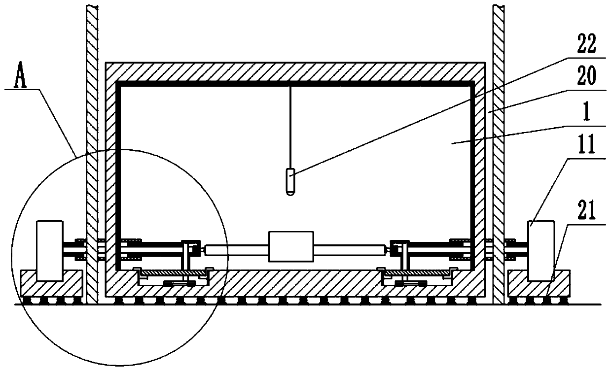
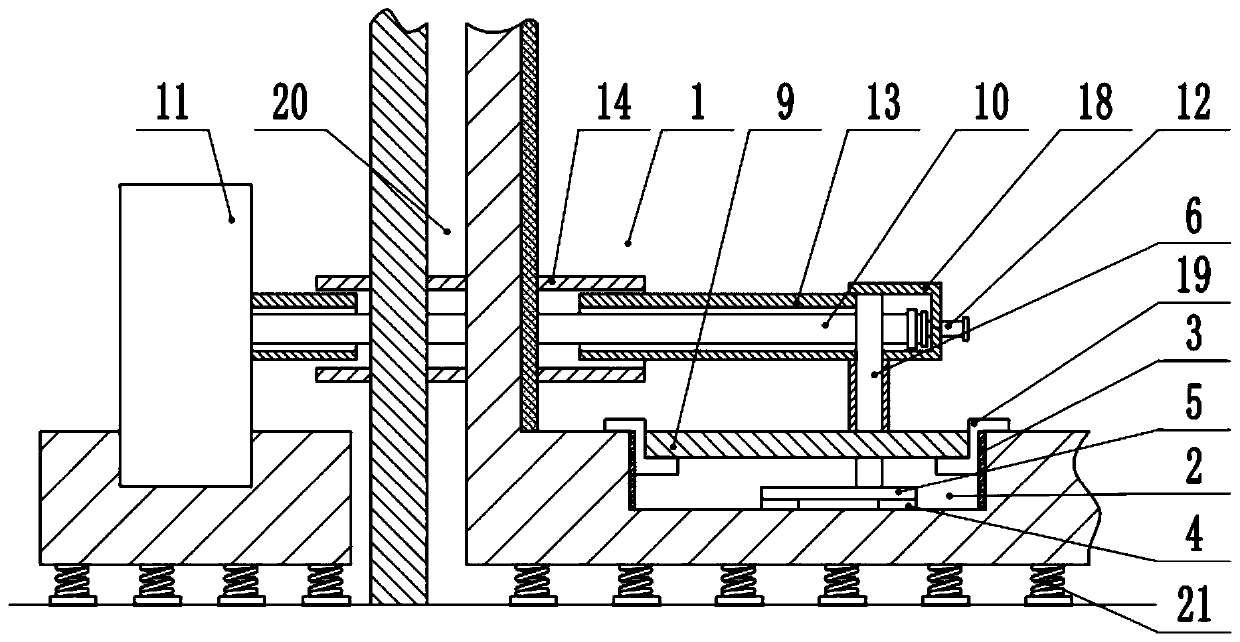
[0033] Basic as attached figure 1 , attached figure 2 and attached image 3 Shown: The noise treatment system for bearing housings used in the NVH test of the pure electric vehicle electric drive system, including a semi-anechoic chamber 1, the wall of the semi-anechoic chamber 1 includes two layers of inner and outer layers, and an air layer 20 is separated between the inner and outer layers of walls . The indoor center of the semi-anechoic chamber 1 is fixed with a microphone 22 suspended in the air for measuring and controlling noise. A damping spring 21 is fixedly connected to the bottom of the semi-anechoic chamber 1, and the end of the damping spring 21 away from the semi-anechoic chamber is fixedly connected to the foundation. The inner wall surface of the semi-anechoic chamber 1 except the ground is fixedly connected with special sound-absorbing components. There is a basement 2 under the ground in the semi-anechoic chamber 1, and the top of the basement 2 communi...

Embodiment 2

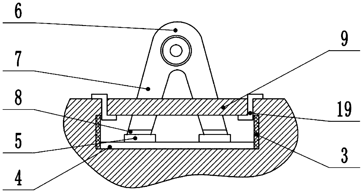
[0038] The difference between this embodiment and Embodiment 1 is that, as Figure 4 As shown, the fixed acoustic component 14 is made of the same material as the movable acoustic component 13, and is divided into an inner layer, a middle layer and an outer layer from inside to outside. The outermost and innermost layers are perforated steel plates 15, the middle layer is a sound-insulating steel plate 16 with a thickness of 2 mm, and sound-absorbing materials are filled between the sound-insulating steel plates 16 and the inner and outer sound-insulating steel plates 16, and the sound-absorbing materials are on the side close to the perforated steel plates 15. Also be provided with nonwoven fabric 17, the thickness of whole structure is controlled at 50~150mm.

[0039] The specific implementation process is as follows: when the sound wave passes through the surface of the fixed acoustic component 14 and the mobile acoustic component 13, the sound wave will pass through the pe...


PUM

PropertyMeasurementUnit
Thicknessaaaaaaaaaa

Abstract

The invention belongs to the technical field of noise testing, and specifically discloses a bearing pedestal noise processing system for NVH test of a pure electric vehicle electric drive system. Thebearing pedestal noise processing system comprises an anechoic chamber, wherein a basement is formed in the ground in the anechoic chamber, the top face of the basement is communicated with the anechoic chamber, an actuating mechanism freely moving in the horizontal direction is fixedly connected into the basement, a bearing pedestal is fixedly connected to the top end of the actuating mechanism,the bottom end of the bearing pedestal is located in the basement, and the top end of the bearing pedestal is higher than the ground of the anechoic chamber; and a dynamometer is arranged outside theanechoic chamber, an output end of the dynamometer is coaxially connected with the bearing pedestal, and the side, away from the dynamometer, of the bearing pedestal serves as a supporting part. The invention aims to provide a noise reduction and sound field optimization system of a bearing pedestal system, so as to solve the problem that noise affects distortion of NVH acquired data.

Description

technical field [0001] The invention belongs to the technical field of testing noise. Background technique [0002] NVH is the abbreviation for Noise, Vibration, Harshness. Under the vigorous promotion of the national new energy policy, the new energy vehicle market has developed rapidly since 2014. To adapt to it, the industry has built an electric drive system NVH semi-elimination room for the new energy vehicle electric drive subsystem and motor components. NVH R & D and production quality control. [0003] In the NVH semi-elimination chamber of the traditional electric drive system, multiple dynamic bearing seats are usually set above the ground, and the electric drive system is supported and connected by the dynamic bearing seats. However, since the bearing seat is exposed outside the semi-anechoic chamber, the effective size of the free sound field of the semi-anechoic chamber is reduced. Secondly, in order to coordinate with the size adjustment in the horizontal pl...

Claims


Application Information

Patent Timeline
IPC IPC(8): G01M17/007G10K11/16
CPCG01M17/007G10K11/16
Inventor 吴建国李沛然邹途祥刘洋山蔡瑞姣
Owner CHINA AUTOMOTIVE ENG RES INST
Why Eureka
Try Eureka