Wire rod phosphating feeding device and working method thereof
A technology of phosphating treatment and wire rod, applied in the direction of metal material coating process, etc., can solve the problems of increased inspection frequency, parameter difference, large workload of employees, etc., to achieve accurate addition, reduce start-up time, save manpower and material resources. Effect
- Summary
- Abstract
- Description
- Claims
- Application Information
AI Technical Summary
Problems solved by technology
Method used
Image
Examples
Embodiment 1
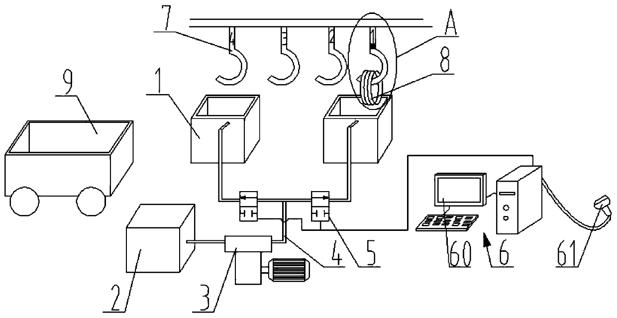
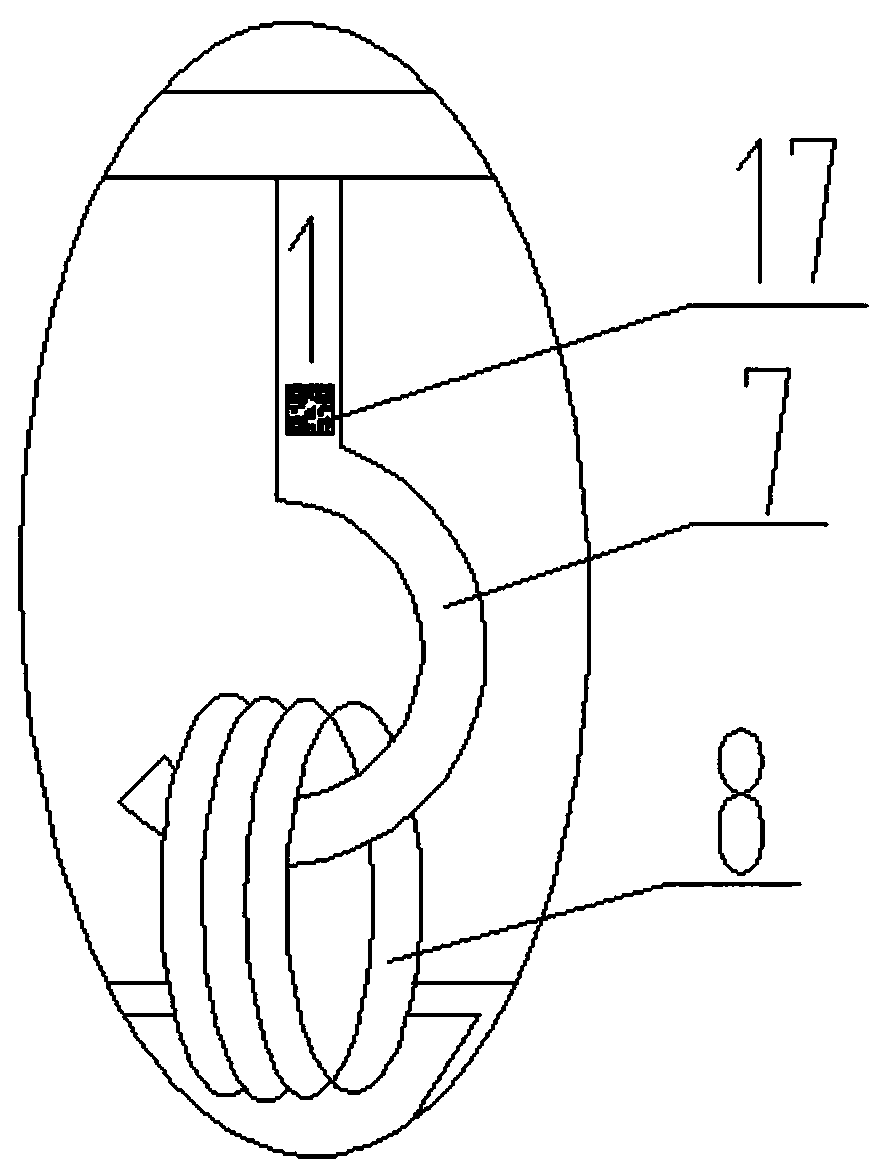
[0054] Such as figure 1 , figure 2As shown, the present invention provides a kind of wire rod phosphating treatment device, comprises phosphating tank 1, phosphating solution tank 2 and metering pump 3, and described phosphating solution tank 2 is arranged on the side of phosphating tank 1, so A liquid delivery pipe 4 is connected between the phosphating solution tank 2 and the phosphating tank 1, and the liquid delivery pipe 4 is provided with an electromagnetic flow valve 5 and a metering pump 3;
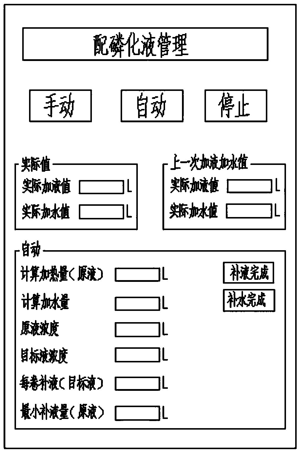
[0055] The wire rod phosphating treatment device also includes a control device 6, the control device 6 includes an operation panel 60, a central processing unit, the central processing unit controls the on-off of the electromagnetic flow valve 5, and the central processing unit presets There is a formula for adding phosphating solution. The flow rate of the electromagnetic flow valve 5 can be selected as 200L / h or 500L / h.
[0056] The wire rod phosphating treatment device inc...
Embodiment 2
[0062] This embodiment provides a working method of a wire rod phosphating treatment device, comprising the following steps:
[0063] (1) The code scanner scans the static two-dimensional code of the wire rod, and enters the basic parameters of the wire rod into the control device;
[0064] (2) Wire rod hanging hook, place the wire rod in the phosphating tank for phosphating treatment, the thickness of the phosphating film on the surface of the wire rod after phosphating treatment is 8g / mm 2 ;
[0065] (3) After the phosphating treatment of the wrapped wire rod is completed, the control device will add phosphating solution to the phosphating tank according to the phosphating solution addition formula (you can choose the phosphating solution stock solution with a total value of 760-780), to ensure the phosphating solution in the phosphating tank Liquid concentration 75-85%;
[0066] (4) The next wire rod is hung with a hook to send the next wire rod to the wire rod phosphatin...
Embodiment 3
[0092] Such as Figure 5 As shown, this embodiment provides a wire rod surface treatment line, the wire rod phosphating treatment device is arranged on the wire rod surface treatment line, and the wire rod surface treatment line includes wire rods arranged in sequence from front to back Pickling device 10, wire rod primary washing device 11, wire rod phosphating treatment device 12, wire rod secondary washing device 13, wire rod saponification device 14 and wire rod drying device 15, a plurality of wire rod suspension hooks 7 are suspended and Walking above the wire rod surface treatment line, a plurality of wire rods 8 are arranged on the feeding trolley 16 before the wire rod pickling device 10, and a plurality of the wire rod suspension hooks 7 hook up the plurality of wire rods 8 one by one. Each of the wire rod hanging hooks 7 is pasted with a static two-dimensional code corresponding to the wire rod 8 it is hooked on, and the static two-dimensional code contains the basi...
PUM
 Abstract
Description
Claims
Application Information
 - R&D
- Intellectual Property
- Life Sciences
- Materials
- Tech Scout
- Unparalleled Data Quality
- Higher Quality Content
- 60% Fewer Hallucinations
Browse by: Latest US Patents, China's latest patents, Technical Efficacy Thesaurus, Application Domain, Technology Topic, Popular Technical Reports.
© 2025 PatSnap. All rights reserved.Legal|Privacy policy|Modern Slavery Act Transparency Statement|Sitemap|About US| Contact US: help@patsnap.com


