
Active carbon adsorption purification system and active carbon adsorption purification method adopting vacuum electric heating regeneration

An activated carbon adsorption and purification system technology, applied in chemical instruments and methods, separation methods, gas treatment, etc., can solve the problems of high regeneration energy consumption, large condensation load, incomplete regeneration, etc., and achieve low regeneration energy consumption and processing load Low maintenance cost effect

Inactive Publication Date: 2020-04-10
张蕾 +1
View PDF8 Cites 3 Cited by
  • Summary
  • Abstract
  • Description
  • Claims
  • Application Information

AI Technical Summary

Problems solved by technology

[0009] In view of the problems existing in the existing adsorption treatment technology using external heating medium regeneration, the present invention provides an activated carbon adsorption purification system and method using vacuum electric heating regeneration, which overcomes the problems of large regeneration energy consumption, incomplete regeneration, and condensation load in the prior art. Large, secondary pollution, deterioration of recyclables, etc., truly realize the recovery and treatment process of organic waste gas "high efficiency, energy saving, safety, economy, zero emissions"

Method used


Image

  • Active carbon adsorption purification system and active carbon adsorption purification method adopting vacuum electric heating regeneration
  • Active carbon adsorption purification system and active carbon adsorption purification method adopting vacuum electric heating regeneration
  • Active carbon adsorption purification system and active carbon adsorption purification method adopting vacuum electric heating regeneration

Examples


Embodiment 1

[0043] Example 1 (vacuum condensation recovery treatment)

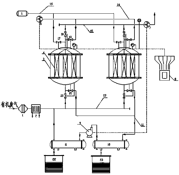
[0044] Such as figure 1 As shown, the activated carbon adsorption and purification system and method using vacuum electrothermal regeneration include a filter 1, a cooler 2, two activated carbon adsorbers 3, an exhaust fan 7, a post-processing system, a cooling fan 5, an air source 6, and a control system 8 , adsorption pipeline 13, desorption pipeline 12, exhaust pipeline 15, cooling pipeline 14, purge pipeline 16; Described activated carbon adsorber shell is provided with pipeline connection port, communicates with each pipeline through valve, and described pipeline connection port is respectively It is arranged at opposite ends of the activated carbon adsorber, one end is provided with waste gas inlet and desorption gas outlet, and the other end is respectively provided with purge gas inlet, purified gas outlet and cooling gas inlet, and the adsorption pipeline 13 is sequentially connected to the filter 1 and the c...

Embodiment 2

[0054] Example 2 (recovery and treatment of vacuum liquid ring)

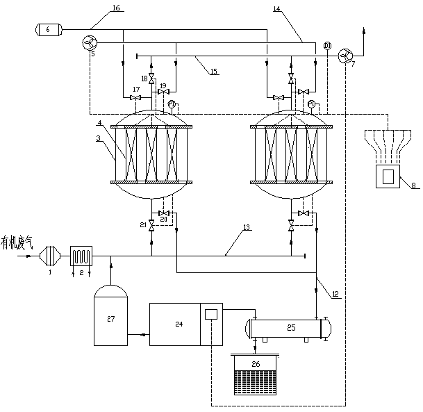
[0055] The activated carbon adsorption and purification system and method using vacuum electrothermal regeneration in this embodiment are as follows: figure 2 As shown, the vacuum aftertreatment system of this embodiment includes a condenser A25, a liquid storage tank A26, a vacuum unit 24 and a gas-liquid separator 27, the air inlet of the condenser A25 communicates with the end of the desorption pipeline 12, and the condenser A25 The liquid outlet is connected with the liquid storage tank A26, the air outlet of the condenser A25 is connected with the air inlet of the vacuum unit 24, the air outlet of the vacuum unit 24 is connected with the air inlet of the gas-liquid separator 27, and the outlet of the gas-liquid separator 27 The gas port communicates with the adsorption pipeline 13, and the vacuum unit includes a liquid ring vacuum pump, a Roots vacuum pump, and a cooler. The working fluid of the liquid rin...

Embodiment 3

[0057] Embodiment 3 (vacuum absorption recovery treatment)

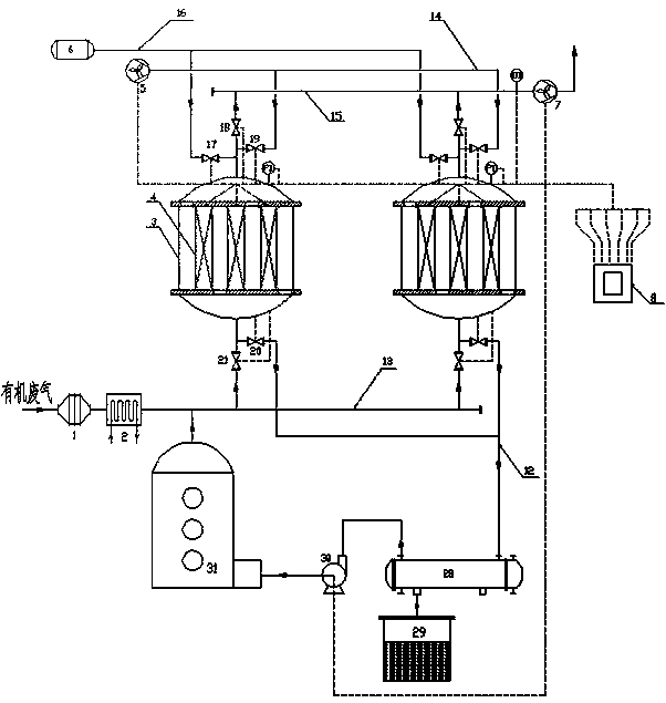
[0058] The activated carbon adsorption and purification system and method using vacuum electrothermal regeneration in this embodiment are as follows: image 3 As shown, the vacuum post-processing system of this embodiment includes a condenser B28, a liquid storage tank B29, a dry vacuum pump B30 and an absorption tower 31. The liquid outlet of the condenser B28 is connected to the liquid storage tank B29, and the gas outlet of the condenser B29 is It is connected with the air inlet of the dry vacuum pump B30, the air outlet of the dry vacuum pump B30 is connected with the air inlet of the absorption tower 31, the air inlet of the condenser B28 is communicated with the end of the desorption pipeline 12, and the air outlet of the absorption tower 31 is connected with the air inlet of the absorption tower 31. Adsorption pipeline 13 communicates.

[0059] The method for absorbing and recovering organic waste gas by usin...


PUM

PropertyMeasurementUnit
widthaaaaaaaaaa

Abstract

The invention discloses an active carbon adsorption purification system and an active carbon adsorption purification method adopting vacuum electric heating regeneration. The system comprises a filter, a cooler and at least more than two active carbon adsorbers, wherein an adsorption purification unit is arranged in the active carbon adsorber, and comprises an active carbon fiber bed layer, electrodes, a temperature sensor and an enclosure structure, the active carbon fiber bed layer is formed by overlapping active carbon fiber fabrics, the temperature sensor is arranged in the bed layer, theelectrodes are arranged on any two opposite end surfaces of the bed layer, and the electrode adopts a mode that an electric-conducting band and an active carbon fiber fabric are overlapped layer by layer or the electric-conducting band and plural layers of active carbon fiber fabrics are overlapped. According to the invention, the electric-conducting bands are uniformly arranged in the end surfacearea of the bed layer to ensure the uniform distribution of the bed layer current in the electric heating process, so that the uniform temperature rise of the active carbon bed layer is realized, organic matter desorption is thorough, regeneration is complete, and the electric heating filtering core can keep good adsorption performance for a long time.

Description

technical field [0001] The invention relates to the technical field of air pollution control, in particular to an activated carbon adsorption purification system and method using vacuum electric heating regeneration. It can be used for industrial VOCs exhaust gas treatment, and can also be used for renewable chemical protection of toxic and harmful gases and purification of VOCs in indoor air. Background technique [0002] At present, the activated carbon adsorption treatment technology widely used in air pollution control projects uses activated carbon as an adsorbent to absorb pollutants in the air. After the activated carbon is saturated, an external heating medium (industrial water vapor, hot nitrogen or hot air) and activated carbon are introduced Perform heat exchange to heat up the activated carbon. During the heating process, the adsorbed pollutants are continuously desorbed from the activated carbon and converted into high-concentration pollutant vapors for condensa...

Claims


Application Information

Patent Timeline
Patent Type & Authority Applications(China)
IPC IPC(8): B01D53/04
CPCB01D53/04B01D53/0454B01D2257/708B01D2259/40086B01D2259/40096
Inventor 张蕾朱军利
Owner 张蕾
Learn More