Oil-water mixture oil separation tank for swill separation and oil separation system thereof
An oil-water mixture and oil tank technology, which is applied in liquid separation, separation methods, auxiliary equipment for liquid separation, etc., can solve the problems of insufficient purity and high water content in the oil, and achieve the effect of reducing water content, high oil content and improving oil content.
- Summary
- Abstract
- Description
- Claims
- Application Information
AI Technical Summary
Problems solved by technology
Method used
Image

Examples
Embodiment 1
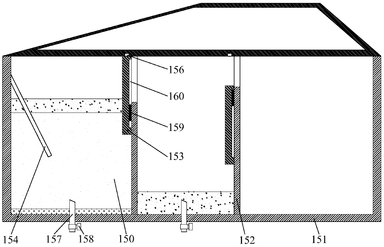
[0064] see figure 1 , This embodiment provides an oil-water mixture separation tank for swill separation, which is used to separate the oil-water mixture so that the liquid is separated into an oil layer and a water layer according to the density. Wherein, the oil-water mixture oil separation tank includes a box body 151, a partition plate 152, a suspension plate 153, a buffer plate 154, a drain pipe 157, a water valve 158, and a material inlet and outlet controller, and may also include a feed pipe 122 and a feed valve 123.
[0065] The box body 151 can be composed of a plurality of assembled boards, and can also be used in an integrally formed structure. The inner and outer surfaces of the box body 151 can be coated with oil-resistant paint, which can ensure that oil stains will not corrode or accumulate on the inner or outer walls of the box body 151 . The tank 151 can be provided with a feed port, and the oil-water mixture / liquid input from the outside enters the tank 151...
Embodiment 2
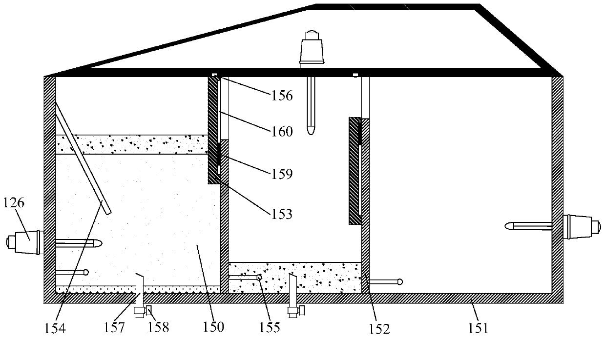
[0078] see figure 2 , the present embodiment provides an oil-water mixture oil separation tank for swill separation, and the oil separation tank adds a heating pipe 126, a temperature sensor 155 and a temperature controller on the basis of Embodiment 1.
[0079] There are multiple heating pipes 126 , and the multiple heating pipes 126 correspond to the multiple oil separation spaces 163 respectively. The heating pipe 126 is installed on the box body 151 and protrudes into the corresponding oil-separating space 163 for heating the oil-water mixture in the corresponding oil-separating space 163 . The heating tube 126 can be an existing heating tube, such as a U-shaped heating tube, which can keep the oil-water mixture in a liquid state all the time, so that the oil-water can be stratified without condensation.
[0080] There are multiple temperature sensors 155 , and each temperature sensor 155 corresponds to one heating tube 126 . The temperature sensor 155 is installed on t...
Embodiment 3
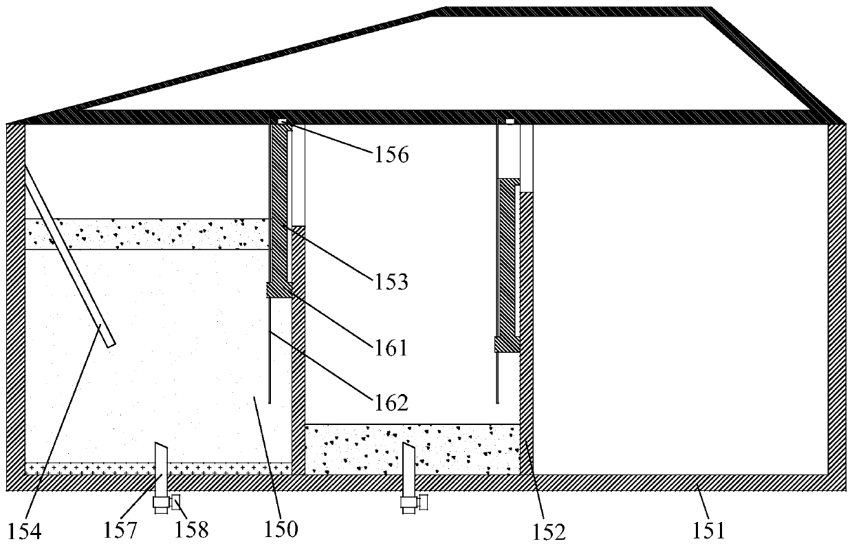
[0084] see image 3 , this embodiment provides an oil-water mixture oil-separation tank for swill separation, which is similar to that of Embodiment 1, except that the structure of the suspension plate 153 and the separator 152 is different. The bottom end of the suspension board 153 has steps 161, and the number of steps 161 is at least one layer. A sliding rod 162 is provided on a side of the partition 152 close to the corresponding suspension plate 153 , the number of the sliding rod 162 is at least one, and each sliding rod 162 corresponds to a step 161 . Each sliding rod 162 passes through the corresponding step 161 and is fixed on the top wall of the box body 151 . Moreover, lubricating oil can be provided at the connecting part of the sliding rod 162 and the sliding rod 162, and a smooth structure can also be used to reduce the friction between the sliding rod 162 and the step 161 and reduce the resistance of the suspension board 153, so that the suspension board 153 c...
PUM
 Abstract
Description
Claims
Application Information
 - Generate Ideas
- Intellectual Property
- Life Sciences
- Materials
- Tech Scout
- Unparalleled Data Quality
- Higher Quality Content
- 60% Fewer Hallucinations
Browse by: Latest US Patents, China's latest patents, Technical Efficacy Thesaurus, Application Domain, Technology Topic, Popular Technical Reports.
© 2025 PatSnap. All rights reserved.Legal|Privacy policy|Modern Slavery Act Transparency Statement|Sitemap|About US| Contact US: help@patsnap.com