Air energy heat pump evaporator structure

An air-energy heat pump and evaporator technology, which is applied in the direction of evaporator/condenser, heat pump, heat exchange equipment, etc. The effect of absorption efficiency and heat exchange efficiency, reducing energy consumption, and increasing contact area

Pending Publication Date: 2020-04-03
贵州嘉予新能源有限公司
View PDF0 Cites 3 Cited by
  • Summary
  • Abstract
  • Description
  • Claims
  • Application Information

AI Technical Summary

Problems solved by technology

Most of the existing evaporators have a structure of heat-absorbing fins and bent tubes. The heat-absorbing fins are made of metal sheets with high thermal conductivity. The fins absorb heat and conduct heat with the bent tubes wound between the fins. To realize the heat exchange of the refrigerant in the elbow, because the metal sheet is very thin, the contact area with the elbow is small, and the heat conduction area is not enough, so the heat exchange efficiency is low. The air is exchanged again, the temperature cannot be locked for a long time, and the temperature changes greatly, which reduces the heat absorption efficiency

Method used


Image

  • Air energy heat pump evaporator structure
  • Air energy heat pump evaporator structure
  • Air energy heat pump evaporator structure

Examples


Embodiment Construction

[0025] The present invention will be further described below in conjunction with the examples, but not as a basis for limiting the present invention.

[0026] Embodiments of the invention

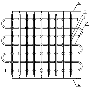
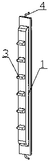
[0027] An air energy heat pump evaporator structure, as attached Figure 1-5 As shown, it includes a number of heat-absorbing fins 1 arranged side by side and a refrigerant conduit 2 interspersed on the heat-absorbing fins 1 in an S shape; each of the heat-absorbing fins 1 is connected by two single-layer metal sheets. into, and is hollow.

[0028] The single-layer heat-absorbing fins are pressed through the mold, and the middle part is pressed out with a pit. The two single-layer heat-absorbing fins are arranged opposite each other, with the pits facing outward. After welding the surroundings of the joints, a hollow heat-absorbing fin can be formed. Fin 1, the heat-absorbing fin 1 is provided with a plurality of through holes for the refrigerant conduit 2 to pass through. During operatio...


PUM


Abstract

The invention discloses an air energy heat pump evaporator structure which comprises multiple heat absorption fins arranged in parallel and a refrigerant guide pipe connected to the heat absorption fins in a penetrating manner in an S shape. Each heat absorption fin is formed by splicing two single-layer metal sheets and is in a hollow shape. The air energy heat pump evaporator structure has the characteristics that the contact area is large, the heat exchange and heat absorption efficiency is high, and the energy consumption is low.

Description

technical field [0001] The invention relates to an air energy heat pump, in particular to an evaporator structure of the air energy heat pump. Background technique [0002] The air energy heat pump uses the energy in the air to generate heat energy. It can provide a large amount of water, high water pressure, and constant temperature 24 hours a day to provide different hot water, cooling and heating needs for the whole family, and at the same time, it can meet the above requirements with the least energy consumption. [0003] The air energy heat pump generally includes an indoor part and an outdoor part, in which the indoor part is a water tank, and the outdoor part is also called an external unit or a peripheral unit, which is mainly used to absorb the temperature in the external environment. The external unit in the prior art is mainly composed of a box, an evaporator, a compressor, a throttle valve and a fan. It adopts a Carnot reverse cycle, and is composed of isothermal...

Claims


Application Information

Patent Timeline
Patent Type & Authority Applications(China)
IPC IPC(8): F25B30/06F28F3/00F28F21/08F25B39/02F28F1/02F25D21/04
CPCF25B30/06F25B39/02F25D21/04F28F1/02F28F3/00F28F21/08
Inventor 刘彬刘震祥刘杨杨光明吴洪江
Owner 贵州嘉予新能源有限公司
Why Eureka
Try Eureka