
Damping device for axial vibration damping and noise reduction of shafting

A damping device, vibration reduction and noise reduction technology, applied in the field of damping devices, can solve the problems of inability to transmit axial thrust, axial vibration of shafting can not be absorbed, and the axial support rigidity of propulsion shafting is small, etc.

Active Publication Date: 2020-03-31
BEIJING UNIV OF CHEM TECH
View PDF6 Cites 2 Cited by
  • Summary
  • Abstract
  • Description
  • Claims
  • Application Information

AI Technical Summary

Problems solved by technology

[0003] At present, there are mainly the following types of axial vibration control for rotating machinery shafting: the patent (CN 102937146A) transmits the axial vibration of the propulsion shafting to the piston, so that the piston moves in the piston chamber, and the piston chamber is filled with hydraulic oil, which can Absorbing vibration; using the magneto-rheological elastomer's magneto-rheological stiffness characteristics to automatically track the external excitation frequency, it can achieve a certain vibration-absorbing effect and apply for a patent (CN 107191529A), but the magnetic permeability of the magnetorheological elastomer is relatively low , the working performance in complex environment is not stable enough
[0004] The above measures will cause the problem that the axial support stiffness of the propulsion shafting is too large or too small. If the stiffness is too large, the axial vibration of the shafting cannot be absorbed; if the stiffness is too small, the axial thrust cannot be transmitted.

Method used


Image

  • Damping device for axial vibration damping and noise reduction of shafting
  • Damping device for axial vibration damping and noise reduction of shafting
  • Damping device for axial vibration damping and noise reduction of shafting

Examples


Embodiment Construction

[0018] The technical solution of the present invention will be described in detail below with reference to the embodiments of the accompanying drawings.

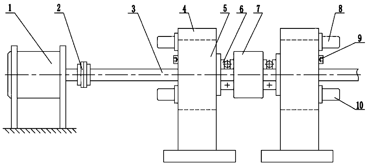
[0019] like figure 1 Shown is a schematic diagram of the basic structure of an embodiment of a damping device for axial vibration and noise reduction of the shaft system of the present invention, including: a stepping motor 1, an elastic coupling 2, a rotating shaft 3, a bearing seat 4, a damping Main body 5, thrust ball bearing 6, thrust plate 7, oil inlet nozzle 8, screw 9 and oil outlet nozzle 10. The motor 1 is connected to the rotating shaft 3 through the elastic coupling 2, and drives the rotating shaft 3 and the thrust disc 7 to rotate together. During the rotation, the rotating shaft 3 will generate axial vibration, which will be transmitted to the main body of the damper through the thrust disc 7 and the thrust ball bearing 6 5, the damper main body 5 will form an oil film damping effect after being squeezed, so as...


PUM


Abstract

The invention discloses a damping device for axial vibration damping and noise reduction of a shafting. The damping device mainly comprises a damper main body and a bearing seat. According to the damping device, a stepping motor drives a rotating shaft to rotate, the rotating shaft is provided with a thrust plate, the axial vibration of the rotating shaft can be transmitted to the damper main bodythrough the thrust plate, hydraulic oil in a gap of the damper main body is subjected to extrusion, an oil film damping effect is formed, so that the axial vibration of the rotating shaft is reducedor weakened, and the damping device belongs to the technical field of vibration control. Two sets of damper assemblies are arranged on the left side and the right side of the thrust plate and are usedfor transmitting and absorbing vibration in the left direction and the right direction respectively. The damping device can be widely applied to the mechanical field with axial vibration, and has theadvantages of excellent vibration damping effect, compact structure and small installation space.

Description

technical field [0001] The invention mainly relates to a damping device for axial vibration reduction and noise reduction of a rotary machine, which is mainly used to solve the problem of axial vibration of the rotary machine in industries such as ships, chemical industry, and electric power, and belongs to the field of vibration control. Background technique [0002] For rotating machines that generate axial force during work, thrust bearings are usually used to withstand or transmit axial thrust, but when the axial force is unstable, axial vibration is often caused. Rotating machinery in shipbuilding, chemical industry, electric power and other industries all have axial vibration problems, such as propulsion shafting of ships, axial vibration is an important factor affecting its concealment. [0003] At present, there are mainly the following types of axial vibration control for rotating machinery shafting: the patent (CN 102937146A) transmits the axial vibration of the pr...

Claims


Application Information

Patent Timeline
IPC IPC(8): F16F15/02F16F15/023F16C35/00
CPCF16C35/00F16F15/022F16F15/0237F16F2230/06
Inventor 何立东范文强闫伟路凯华李耕
Owner BEIJING UNIV OF CHEM TECH
Learn More