
Printing head, printing method, printing system, storage medium and printer

A printing head and nozzle technology, which is applied in casting molding equipment, metal processing equipment, casting molds, etc., can solve problems such as hindering board work, affecting work efficiency and work accuracy, and affecting board work, so as to ensure normal and stable work. Effect

Pending Publication Date: 2020-03-31
KOCEL INTELLIGENT FOUNDRY IND INNOVATION CENT CO LTD
View PDF0 Cites 8 Cited by
  • Summary
  • Abstract
  • Description
  • Claims
  • Application Information

AI Technical Summary

Problems solved by technology

[0002] In the print head part of 3DP sand core printer, the control board is a precision component, and the working temperature requirement is high. When the control board works, it will generate a lot of heat. Excessive heat will affect the life of the board, and the board is expensive, which will increase Printing cost, the current one is an open structure, and the printing materials will have dust phenomenon, the dust adheres to the control board and other precision components in the print head, and also adheres to the inside of the nozzle, so that being covered by dust will hinder the work of the board , the dust cleaning work is more complicated, on the one hand, it will affect the follow-up board work, on the other hand, it will affect the work efficiency and work accuracy

Method used


Image

  • Printing head, printing method, printing system, storage medium and printer
  • Printing head, printing method, printing system, storage medium and printer
  • Printing head, printing method, printing system, storage medium and printer

Examples


Embodiment 1

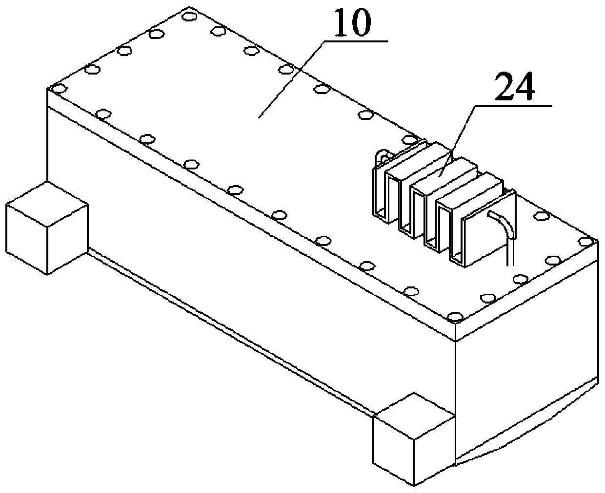
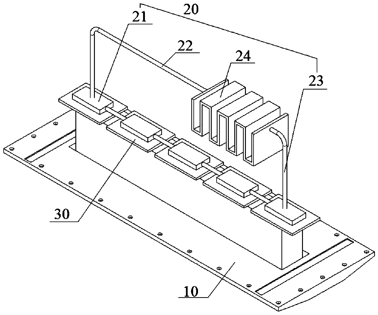
[0129] Refer to attached figure 1 And attached figure 2 As shown, a print head includes a housing 10, a thermostat 20 and a board 30, the thermostat 20 is in contact with the board 30, and the thermostat 20 includes a heat exchange block 21, a liquid inlet pipe 22, an outlet Liquid pipe 23, No. 1 circulation pump, and No. 1 radiator 24. One end of the heat exchange block 21 communicates with the liquid inlet pipe 22, and the opposite end communicates with the liquid outlet pipe 23. The No. 1 radiator 24 One end is communicated with the described liquid inlet pipe 22, and the opposite end of the No. 1 radiator 24 is communicated with the described liquid outlet pipe 23, and the described liquid inlet pipe 22 or the described liquid outlet pipe 23 is provided with the No. 1 circulation pump, the No. 1 radiator 24, the liquid inlet pipe 22, the heat exchange block 21, the liquid outlet pipe 23, and the No. 1 circulation pump are connected to form a cooling passage; the casing 1...

Embodiment 2

[0133] On the basis of embodiment 1, a kind of printing head also comprises ink heating device 40, and described ink heating device 40 comprises ink cartridge 41, ink inlet pipe 42, ink outlet pipe 43, No. 2 circulation pump, and described ink cartridge 41 is arranged on Inside the housing 10, one end of the heat exchange block 21 communicates with the ink inlet pipe 42, and the opposite end communicates with the ink outlet pipe 43, and one end of the ink cartridge 41 communicates with the ink inlet pipe 42, And the opposite end of the ink cartridge 41 communicates with the ink outlet pipe 43, the No. 2 circulation pump is set on the ink inlet pipe 42 or the ink outlet pipe 43, the ink cartridge 41, the ink inlet pipe 42. The heat exchange block 21, the ink outlet pipe 43, and the No. 2 circulating pump are connected to form an ink heating passage.

[0134] The heat exchange block 21 includes an ink pipeline 210 and a liquid pipeline 211. The ink pipeline 210 is in a zigzag sh...

Embodiment 3

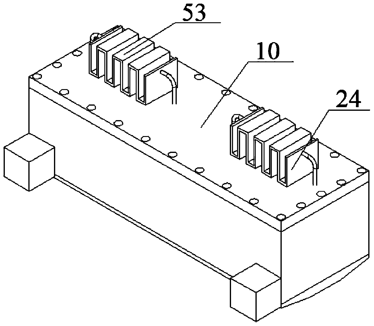
[0137] Refer to attached image 3 and 4As shown, on the basis of Embodiment 2, a print head further includes an ink cooling device 50, and the ink cooling device 50 includes an ink supply tube 51, an ink delivery tube 52, a No. 3 circulation pump, and a No. 2 radiator 53. The No. 2 radiator 53 is arranged outside the housing 10, one end of the ink cartridge 41 communicates with the ink supply tube 51, and the opposite end communicates with the ink delivery tube 52. The No. 2 radiator communicates with the ink supply tube 51. One end of 53 communicates with the ink supply pipe 51, and the opposite end communicates with the ink supply pipe 52. The No. 3 circulation pump is arranged on the ink supply pipe 51 or the ink supply pipe 52, and the The ink cartridge 41 , the ink supply pipe 51 , the No. 2 radiator 53 , the ink delivery pipe 52 , and the No. 3 circulating pump are connected to form an ink cooling passage.


PUM

PropertyMeasurementUnit
thicknessaaaaaaaaaa

Abstract

Provided are a printing head, a printing method, a printing system, a storage medium and a printer. The printing head comprises a shell, a constant temperature device and a board card, wherein the constant temperature device is in contact with the board card; the constant temperature device comprises a heat exchange block, a liquid inlet pipe, a liquid outlet pipe, a first circulating pump and a first radiator; one end of the heat exchange block communicates with the liquid inlet pipe, and the other end, opposite to the former end, of the heat exchange block communicates with the liquid outletpipe; one end of the first radiator communicates with the liquid inlet pipe, and the other end, opposite to the former end, of the first radiator communicates with the liquid outlet pipe; the first circulating pump is arranged on the liquid inlet pipe or the liquid outlet pipe; the first radiator, the liquid inlet pipe, the heat exchange block, the liquid outlet pipe and the first circulating pump communicate to form a cooling passage; and the shell encloses a space, the heat exchange block and the board card are both arranged inside the shell, and the first radiator is arranged outside the shell. The working temperature of the board card is guaranteed, and the service life of a precision component is prolonged.

Description

technical field [0001] The invention relates to the field of additive manufacturing 3D printing equipment, in particular to a printing head, a printing method, a printing system, a storage medium and a printing equipment. Background technique [0002] In the print head part of 3DP sand core printer, the control board is a precision component, and the working temperature requirement is high. When the control board works, it will generate a lot of heat. Excessive heat will affect the life of the board, and the board is expensive, which will increase Printing cost, the current one is an open structure, and the printing materials will have dust phenomenon, the dust adheres to the control board and other precision components in the print head, and also adheres to the inside of the nozzle, so that being covered by dust will hinder the work of the board , The dust cleaning work is more complicated. On the one hand, it will affect the subsequent board work, and on the other hand, it...

Claims


Application Information

Patent Timeline
Patent Type & Authority Applications(China)
IPC IPC(8): B29C64/20B29C64/386B29C64/393B33Y30/00B33Y50/00B33Y50/02B22C9/10
CPCB29C64/20B29C64/386B29C64/393B33Y30/00B33Y50/00B33Y50/02B22C9/10Y02P10/25
Inventor 虎鑫蒙南华闫涛王军伟马玺孙旺彭凡刘轶
Owner KOCEL INTELLIGENT FOUNDRY IND INNOVATION CENT CO LTD
Learn More