
Power device active junction temperature control system and method

A technology for power devices and control systems, applied in the field of active junction temperature control systems for power devices, can solve the problems of reduced reliability and life of converters, high average junction temperature levels of power devices, and excessive junction temperature fluctuation amplitudes. , to achieve the effect of short adjustment time, optimized control strategy, and reduced junction temperature fluctuation level

Active Publication Date: 2020-03-27
CSR ZHUZHOU ELECTRIC LOCOMOTIVE RES INST
View PDF7 Cites 8 Cited by
  • Summary
  • Abstract
  • Description
  • Claims
  • Application Information

AI Technical Summary

Problems solved by technology

[0006] In view of this, the purpose of the present invention is to provide a power device active junction temperature control system and method to solve the problem that the average junction temperature level of power devices is too high, and the junction temperature fluctuation amplitude is too large to cause the overall reliability and life of the converter. Reduced technical issues

Method used


Image

  • Power device active junction temperature control system and method
  • Power device active junction temperature control system and method
  • Power device active junction temperature control system and method

Examples


Embodiment 1

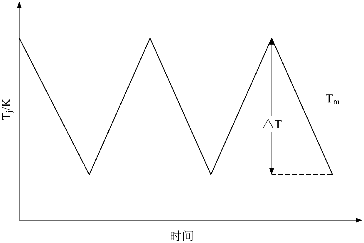
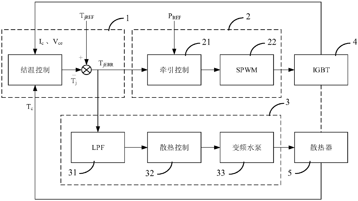
[0049] via as attached image 3 The embodiment shown, to reduce the junction temperature fluctuation amplitude ΔT and the average junction temperature T m controlled within a reasonable range. An active junction temperature control system for a power device, specifically comprising: a junction temperature control unit 1 , a junction temperature control link 2 , a case temperature control link 3 , a power device 4 and a radiator 5 . The junction temperature control unit 1 is based on the real-time junction temperature T of the power device 4 j with a given junction temperature T jREF The difference T jERR Calculate and output the control quantity to the crust temperature control link 2 and the shell temperature control link 3. The junction temperature control link 2 is based on the real-time junction temperature T of the power device 4 j with a given junction temperature T jREF The difference T jERR and traction control input signal P REF Calculate the traction control ...

Embodiment 2

[0055]as attached Figure 4 As shown, an embodiment of a method for active junction temperature control of a power device specifically includes the following steps:

[0056] S11) According to the real-time junction temperature T of the power device 4 j with a given junction temperature T jREF The difference T jERR and traction control input signal P REF Calculate the traction control signal output to the power device 4, by calculating the temperature T between the junction and the case of the power device 4 during operation jc Perform active control to reduce the average junction temperature T of the power device 4 m and junction temperature fluctuation amplitude △T j ;

[0057] S12) According to the real-time junction temperature T of the power device 4 j with a given junction temperature T jREF The difference T jERR Calculate the control value output to the frequency conversion water pump 33, actively control the thermal resistance of the radiator 5 by adjusting the...


PUM


Abstract

The invention provides a power device active junction temperature control system and method. The system comprises a junction temperature control unit, a junction temperature control link, a shell temperature control link, a power device and a radiator. The junction temperature control unit calculates and outputs a control quantity to the crust temperature control link and the shell temperature control link according to the difference between the real-time junction temperature of the power device and a given junction temperature. The junction temperature control link calculates a traction control signal output to the power device according to the control quantity output by the crust temperature control unit and the traction control input signal, and actively controls the temperature betweencrusts of the power device. The shell temperature control link calculates a control value output to the variable frequency water pump according to the control quantity output by the junction temperature control unit, and actively controls the thermal resistance of the radiator by adjusting the water outlet flow of the variable frequency water pump. The technical problems that the overall reliability of the converter is reduced and the service life of the converter is shortened due to over-high working average junction temperature level and over-large junction temperature fluctuation amplitudeof the power device can be solved.

Description

technical field [0001] The present invention relates to the field of power electronics technology, in particular to a power device that integrates junction-case temperature control and heat dissipation link case temperature control technology to effectively control the active junction temperature level and junction temperature fluctuation amplitude of converter power devices Active junction temperature control system and method. Background technique [0002] In recent years, as a key equipment in the field of rail transit - traction converters have developed rapidly in China. Specific application fields require converters to have high reliability. Among them, the power converter is the core component of the converter, and its reliability determines the safety of the application. At present, statistical results from a large number of traction system faults in rail transit applications show that converter faults account for a large proportion of the entire traction system fau...

Claims


Application Information

Patent Timeline
Patent Type & Authority Applications(China)
IPC IPC(8): G05D23/19H02M1/00H01L23/473
CPCG05D23/19H02M1/00H01L23/473
Inventor 刘文业李彦涌赖伟陈燕平刘永江李斌杜凯冰何凯李冬蕾
Owner CSR ZHUZHOU ELECTRIC LOCOMOTIVE RES INST
Learn More