
New and old pavement base lap joint structure

A pavement base layer and joint structure technology, which is applied to roads, roads, pavement details, etc., can solve the problems of easy gaps at the joints of old and new pavements, and achieve the effect of enhancing the firmness of the connection and firm connection

Inactive Publication Date: 2020-03-27
武汉市武昌市政建设(集团)有限公司
View PDF9 Cites 4 Cited by
  • Summary
  • Abstract
  • Description
  • Claims
  • Application Information

AI Technical Summary

Problems solved by technology

[0004] The above-mentioned existing technical solutions have the following defects: since there is no gap between the old pavement surface and the new pavement surface, and the main material of the old pavement surface and the new pavement surface is still concrete, in hot weather or cold weather, Concrete will expand with heat and contract with cold, so it will directly lead to gaps at the joints of old and new pavements, so it needs to be improved

Method used


Image

  • New and old pavement base lap joint structure
  • New and old pavement base lap joint structure
  • New and old pavement base lap joint structure

Examples


Embodiment 1

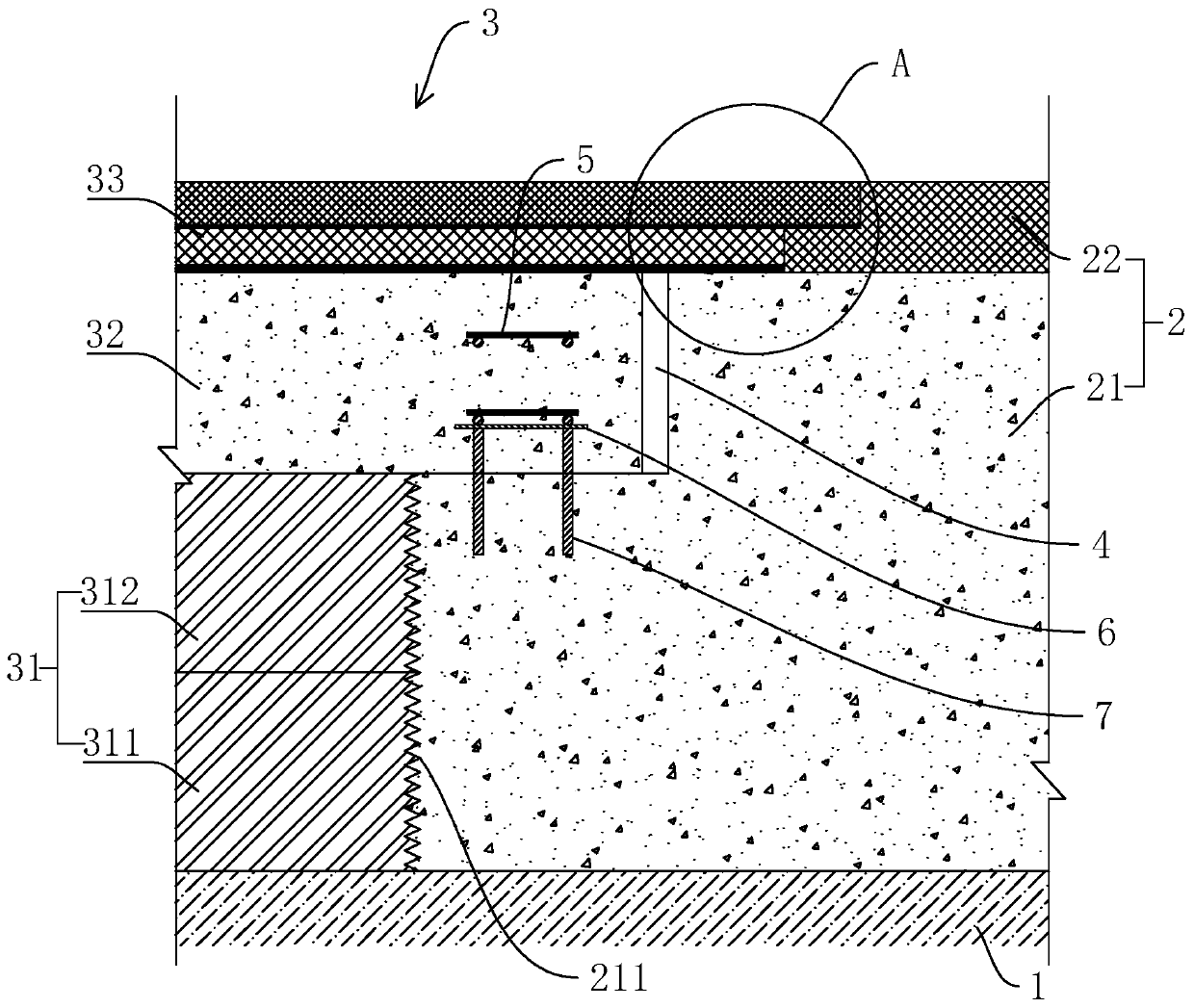
[0037] refer to figure 1 , is a new and old pavement base overlapping structure disclosed by the present invention, comprising: a subgrade 1, an old pavement main body 2 and a new pavement main body 3.

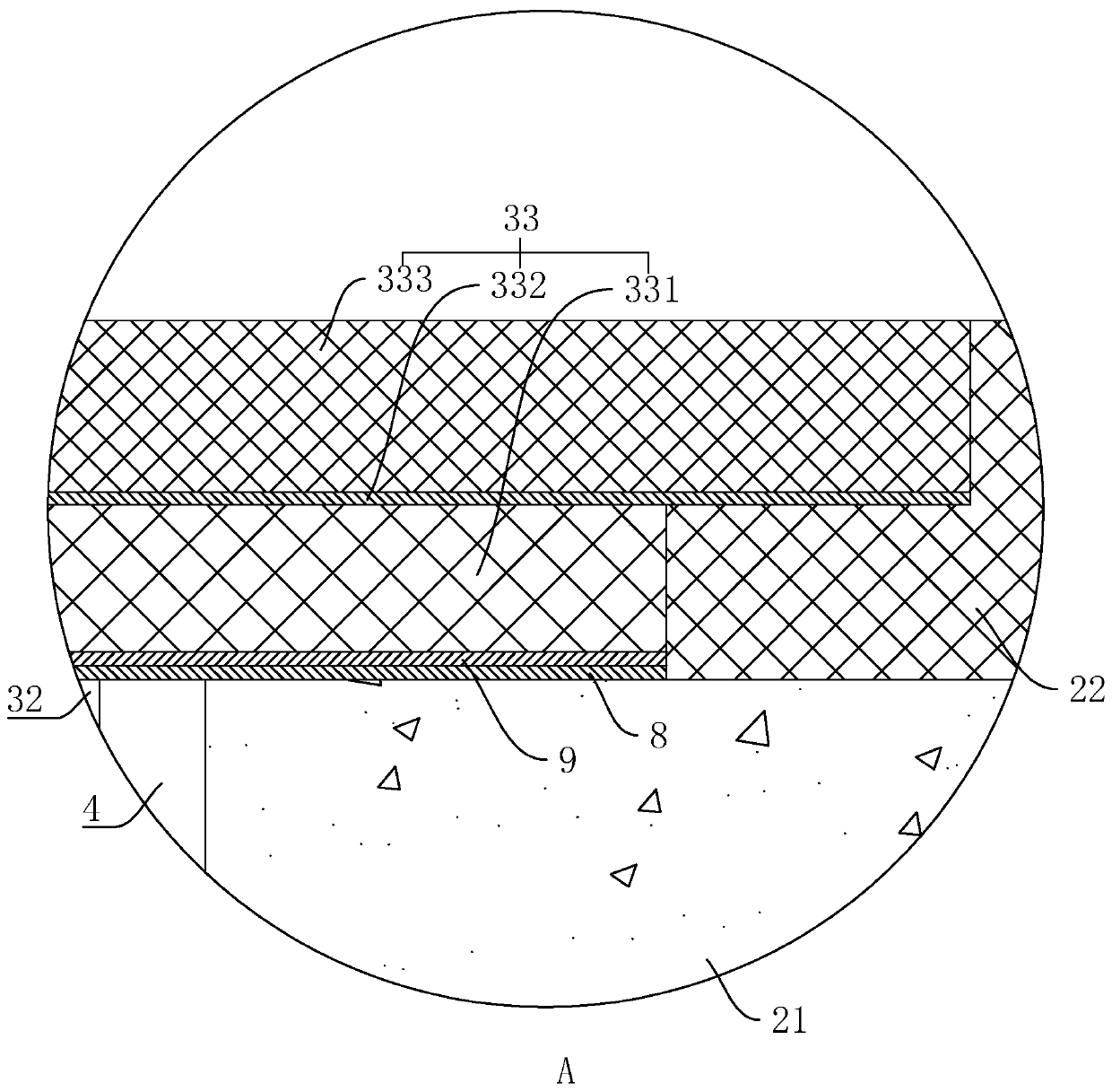
[0038]The old road surface main body 2 and the new road surface main body 3 are all arranged on the subgrade 1. The old road surface main body 2 includes an old road support layer 21 and an old road surface layer 22 laid sequentially from bottom to top. The end face of the old road support layer 21 is excavated with a first Steps, a second step is formed between the end face of the old road support layer 21 and the end face of the old road surface layer 22, and a third step is excavated on the end face of the old road surface layer 22, the first step, the second step, and the third step step by step Heightening; new road surface main body 3 includes: new road base layer 31, new road support layer 32 and new road surface layer 33, new road support layer 32 is formed by laying c...

Embodiment 2

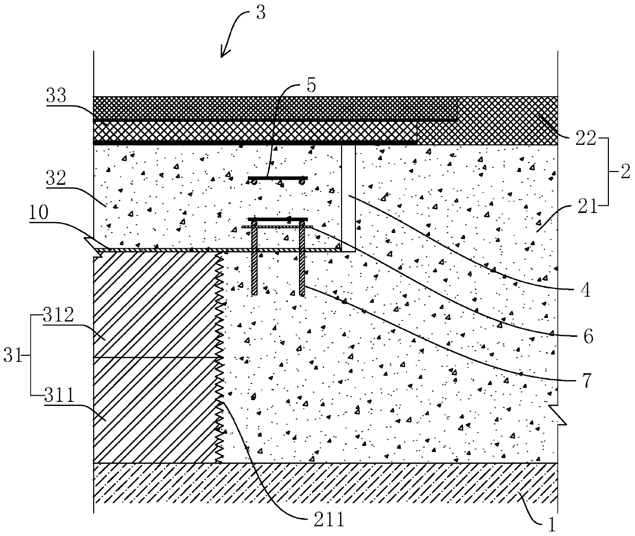
[0053] refer to image 3 , is a new and old pavement base overlapping structure disclosed by the present invention, and the difference from Embodiment 1 is that a layer of glass fiber cloth 10 is laid on the upper surface of the new road base 31 and the bottom surface of the first step, and then A new road support layer 32 is formed on the glass fiber cloth 10. The glass fiber cloth 10 has high strength, corrosion resistance, and is not easy to be torn, so the glass fiber cloth 10 further enhances the connection strength of the old and new pavement seams and is more durable.


PUM


Abstract

The invention relates to the technical field of road traffic engineering construction, in particular to a new and old pavement base lap joint structure which comprises a roadbed, an old pavement bodyand a new pavement body, wherein the old pavement main body and the new pavement main body are both arranged on a roadbed, the old pavement main body comprises an old pavement supporting layer and anold pavement layer, a first step is excavated on the end surface of the old pavement supporting layer, a second step is formed between the end surface of the old pavement supporting layer and the endsurface of the old pavement layer, and a third step is excavated on the end surface of the old pavement layer; the new pavement main body comprises: a new pavement main body; a new roadbed layer, a new road support layer and a new pavement layer, the upper surface of the new roadbed layer is flush with the bottom surface of the first step; the new road supporting layer is laid on the upper surfaceof the new road base layer and the bottom face of the first step, expansion joints are reserved between the end face of the new road supporting layer and the side face of the first step, the new roadsurface layer is laid on the upper surface of the new road supporting layer, and the end face of the new road surface layer is attached to the end face of the old road surface layer. The method has the effect that joints of new and old pavements are not prone to generating gaps.

Description

technical field [0001] The invention relates to the technical field of road traffic engineering construction, in particular to a new and old pavement base overlapping structure. Background technique [0002] With the development of society and economy, the traffic volume of expressways is increasing day by day, and the traffic volume of some expressways has reached saturation, and the congestion phenomenon is serious. In order to solve this phenomenon, widening expressways is an economical and effective way. In most cases, road widening requires lapping of old and new asphalt pavement. [0003] A Chinese invention patent with a notification number of CN107178018A has been retrieved, which discloses a new and old asphalt pavement overlapping structure, including old pavement, new pavement, modified hot asphalt, polyester fiberglass cloth and anti-cracking stickers. The old pavement It includes an old pavement base and an old pavement surface, and the edge of the old pavement...

Claims


Application Information

Patent Timeline
Patent Type & Authority Applications(China)
IPC IPC(8): E01C11/02E01C3/00
CPCE01C3/00E01C11/02E01C2201/167
Inventor 王军民范南征王小艳彭疆原
Owner 武汉市武昌市政建设(集团)有限公司
Learn More