Foil type coil winding die with air channel
A foil and coil technology, applied in coil manufacturing, electrical components, inductance/transformer/magnet manufacturing, etc., can solve the problem of inability to place foil coils in the airway, achieve simple structure, convenient winding and molding, and improve production. The effect of efficiency
- Summary
- Abstract
- Description
- Claims
- Application Information
AI Technical Summary
Problems solved by technology
Method used
Image

Examples
Embodiment 1
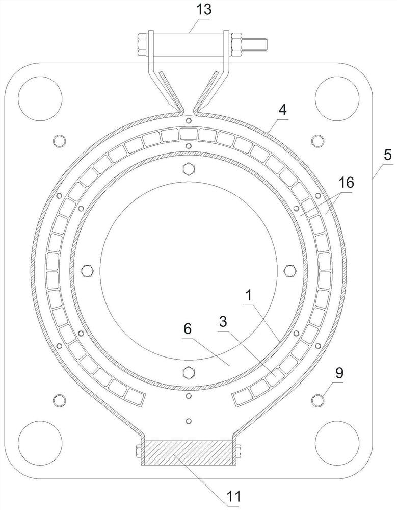
[0031] Such as Figure 1-Figure 8 As shown, a foil coil winding mold with an air channel includes an inner mold 1, an air channel rod positioning plate 2, an air channel rod 3, an outer mold 4, an end template 5, and an inner mold leading positive mold 6;
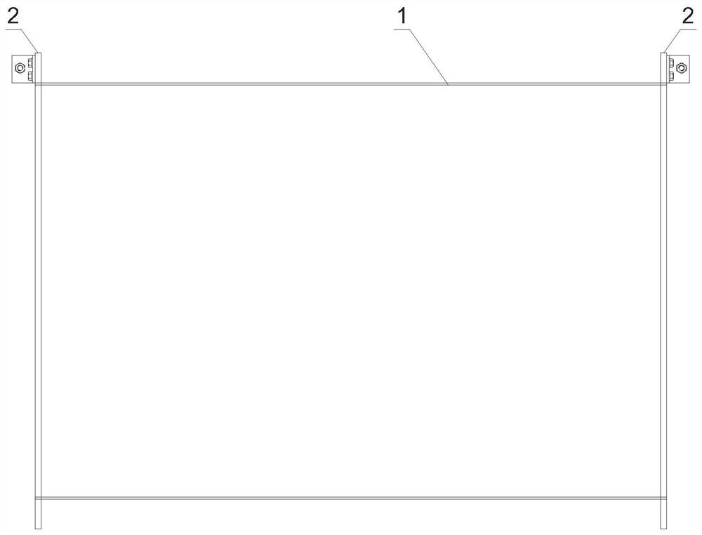
[0032] The inner mold 1 is cylindrical, and the two ends of the inner mold 1 are respectively fixed with an annular airway stick positioning plate 2, and the end surface of the airway stick positioning plate 2 is provided with a mounting hole 201 for fixing the airway stick 3, and the two airway sticks A plurality of airway rods 3 are evenly fixed between the mounting holes 201 of the positioning plate 2, and the plurality of airway rods 3 form an airway rod layer outside the inner mold 1;
[0033] The lower layer winding 7 is wound between the airway rod layer and the inner mold 1, and the upper layer winding 8 is wound outside the airway rod layer;
[0034] The outer mold 4 is set outside the inner mold 1 after the windi...
Embodiment 2
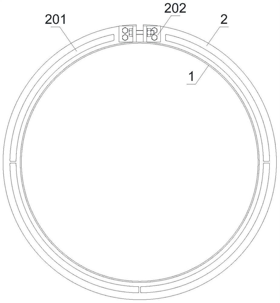
[0044] Such as figure 2 , image 3 As shown, the airway rod positioning plate 2 is an annular plate provided with an intermittent joint 202, the annular plate is placed on the end of the inner mold 1, and the airway rod positioning plate 2 is fixed on the inner mold 1 by locking the intermittent joint 202 with screws .
[0045] The airway stick positioning plate 2 is provided with four sections of C-shaped arc holes equally divided with the same center, and the C-shaped arc holes are used as the installation holes 201 of the airway stick 3 . Other structures are the same as in Embodiment 1.
[0046] The airway stick positioning plate 2 is an annular plate provided with intermittent joints 202, and has few fastening screws, which is convenient for installation on the inner mold 1 and for easy disassembly; the C-shaped circular arc hole with the same center is used to facilitate the installation of the airway stick 3 . The spacing of the airway rods 3 can be set as required...
Embodiment 3
[0048] Such as Image 6 As shown, the outer mold 4 and the end template 5 are locked and fixed by a long screw 9 outside the outer mold 4 .
[0049] A silicone rubber sealing plate 10 is used to seal between the ends of the inner mold 1 , the outer mold 4 and the end template 5 .
[0050] An annular positioning template 16 is provided inside the silicone rubber sealing plate 10 , and a positioning template 16 is respectively provided between the outer circumference of the inner mold 1 and the airway rod 3 , and between the inner circumference of the outer mold 4 and the airway rod 3 . The positioning template 16 plays a guiding role, so that the inner mold 1 and the outer mold 4 are poured to form a regular circle.
[0051] One side of the outer mold 4 is provided with a branch wiring template 11, on which the wiring insert 12 (inserts such as tap nuts) is fixed, and the wiring insert 12 is electrically connected with the upper winding 8 and the lower winding 7.
[0052] The...
PUM
 Abstract
Description
Claims
Application Information
 - R&D
- Intellectual Property
- Life Sciences
- Materials
- Tech Scout
- Unparalleled Data Quality
- Higher Quality Content
- 60% Fewer Hallucinations
Browse by: Latest US Patents, China's latest patents, Technical Efficacy Thesaurus, Application Domain, Technology Topic, Popular Technical Reports.
© 2025 PatSnap. All rights reserved.Legal|Privacy policy|Modern Slavery Act Transparency Statement|Sitemap|About US| Contact US: help@patsnap.com