
Quasi-telecentric high-power optical focusing lens for laser welding machine and imaging method of quasi-telecentric high-power optical focusing lens

An optical focusing lens, laser welding machine technology, applied in laser welding equipment, optics, condenser lens and other directions, can solve the problems of affecting welding quality and welding speed, affecting welding quality and precision, large lens energy loss, etc., to achieve energy concentration, The effect of increasing the entrance pupil diameter and relative aperture and improving energy utilization

Active Publication Date: 2020-03-24
SUZHOU UNIV
View PDF7 Cites 4 Cited by
  • Summary
  • Abstract
  • Description
  • Claims
  • Application Information

AI Technical Summary

Problems solved by technology

Chinese invention patent CN109633864A provides a telecentric lens for laser processing in the ultraviolet band. The lens includes five lenses, the first of which is a double-concave negative lens, the second is a meniscus negative lens, and the third is a meniscus. Positive lens, the fourth piece is a biconvex positive lens, the fifth piece is a plano-convex positive lens, the focal length of the lens is 74mm, the diameter of the entrance pupil is 10mm, and the F number is 7.4; it is not difficult to find that the existing far Cardiofocus lenses have the following disadvantages: (1) Most of them are used in the ultraviolet band, but rarely seen in laser welding machines in the near-infrared band; (2) The diameter of the entrance pupil and the relative aperture are small, and the diameter of the entrance pupil is generally less than 15mm. F / # is greater than 8; (3) The lens design uses a large number of lenses, and some even improve the performance of the lens by adding aspheric surfaces, resulting in large energy loss and low power of the lens, which affects the further improvement of welding quality and welding speed
The Chinese invention patent with the publication number CN 104813214 A discloses a near-infrared focusing lens, which is a near-infrared laser focusing lens for laser printing equipment. The lens includes five lenses, wherein the first lens is a plano-concave negative lens , the second and third lenses are biconvex positive lenses, the fourth and fifth lenses are meniscus positive lenses, the focal length of the lens is f=19mm, the F number is 0.85, and the field of view is 2ω=12°; this lens belongs to near-infrared laser cutting The F-θ lens is a microscopic objective lens with a large field of view and a large relative aperture. The disadvantages of this lens are: (1) the number of lenses is large, and the energy loss of the lens is large; (2) because the lens has no Set the image square telecentric structure, there is a problem that the chief light is not perpendicular to the working surface during the scanning process, if it is used in the galvanometer laser welding machine, it will lead to severe penetration and fusion width at the middle and edge of the workpiece during the welding process Changes, making the weld width inconsistent, affecting the quality and accuracy of welding

Method used


Image

  • Quasi-telecentric high-power optical focusing lens for laser welding machine and imaging method of quasi-telecentric high-power optical focusing lens
  • Quasi-telecentric high-power optical focusing lens for laser welding machine and imaging method of quasi-telecentric high-power optical focusing lens
  • Quasi-telecentric high-power optical focusing lens for laser welding machine and imaging method of quasi-telecentric high-power optical focusing lens

Examples


Embodiment 1

[0028] Embodiment 1: The technical solution of this embodiment is to provide an optical focusing lens and an imaging method thereof for a vibrating mirror laser welding machine. The focal length of the optical focusing lens is f=150mm, the F number F / #=6, the scanning angle θ=±15°, the working wavelength is 1.064μm, the aperture diaphragm is located at the focal plane of the lens, and the X scanning galvanometer to the Y scanning Galvanometer distance d x,y =21mm, the distance d from the Y scanning galvanometer to the front surface of the first lens according to the light incident direction y,1 =40mm.

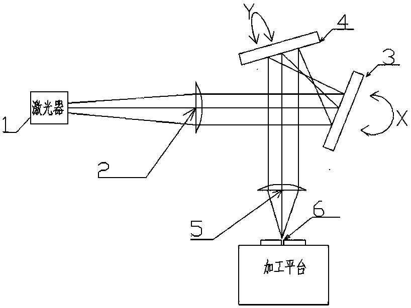
[0029] See attached figure 1, which is the working principle diagram of the laser welding machine. After the beam expansion of the laser 1 passes through the collimation system 2, it enters the X galvanometer 3 for deflection of the light in the X direction, and then enters the Y galvanometer 4 for Y The light in the direction is deflected, and finally, the light is focused ...


PUM

PropertyMeasurementUnit
Entrance pupil diameteraaaaaaaaaa
Field of viewaaaaaaaaaa

Abstract

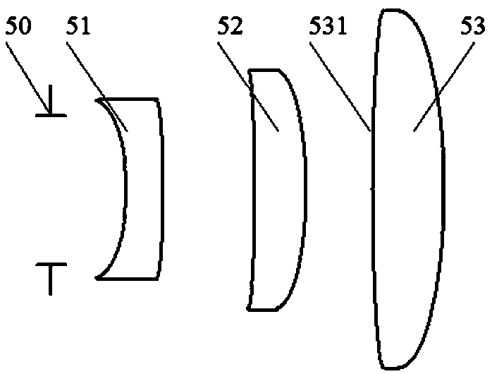
The invention discloses a quasi-telecentric high-power optical focusing lens for a laser welding machine and an imaging method of the quasi-telecentric high-power optical focusing lens. The focusing lens is composed of three refraction lenses, and the focal powers of the lenses are negative, positive and positive in sequence in the incident direction of light. The front two lenses are bent towardsthe light incident direction, and the front surface of the third lens is opposite to the light incident direction. The glass refractive indexes of the three lenses are sequentially n51, n52 and n53,n51 is larger than or equal to 1.20 and smaller than or equal to 1.80, and n52 is larger than or equal to 1.50 and smaller than or equal to 2.15. The relative aperture of the focusing lens is larger,and the focusing performance is close to a diffraction limit, so that the power of a system is higher, and the working area can reach phi 150mm. The quasi-telecentric structure of the lens can avoid the violent change of the shape of a weld joint caused by slight defocusing or inclination of a machined workpiece, a large-aperture laser beam can be focused on the working face of the workpiece to bewelded, the larger fusion depth and fusion width are obtained, and the precise welding of the laser welding machine is achieved.

Description

technical field [0001] The invention relates to a quasi-telecentric high-power optical focusing lens for a laser welding machine and an imaging method thereof, in particular to a method for focusing a large-aperture laser beam on the working surface of a workpiece to be welded to obtain greater penetration and Melting width, optical focusing lens and imaging method suitable for laser welding. Background technique [0002] Commonly used laser welding machines in industry include galvanometer laser welding machines, laser spot welding machines, automatic laser welding machines, mold laser welding machines, etc. Among them, the laser galvanometer welding machine is usually used in welding occasions with high welding process requirements and convenient optical path movement, such as welding of precision parts such as microelectronic components and integrated circuit leads. See attached figure 1 , which is a schematic diagram of the working principle of the galvanometer laser w...

Claims


Application Information

Patent Timeline
IPC IPC(8): G02B19/00B23K26/06
CPCG02B19/0014G02B19/0047B23K26/0648Y02P70/10
Inventor 季轶群高艳红曹冰谭奋利
Owner SUZHOU UNIV
Learn More