Board-mode program-controlled voltage bias test circuit of large-scale digital integrated circuit

An integrated circuit and program-controlled voltage technology, which is applied in the field of board-type program-controlled voltage biasing test circuits, can solve the problems of being inconvenient to carry, unable to use biasing tests, and unable to realize automated tests, and achieves excellent portability and complete automation. The effect of the pull-off test

Pending Publication Date: 2020-03-24
CHINA ACADEMY OF SPACE TECHNOLOGY
View PDF0 Cites 0 Cited by
  • Summary
  • Abstract
  • Description
  • Claims
  • Application Information

AI Technical Summary

Problems solved by technology

[0003] (1) The main problem of using a special program-controlled power supply instrument is that the volume and weight of the instrument are generally large, and it is not easy to carry during the test, especially when the operating voltage of the integrated circuit is more than 4 circuits (such as Xilinx 7 series FPGA , need VCCINT, VCCAUX, VCCAUX_IO, VCCO of different banks, VCCBRAM, VREF, MGTAVCC, MGTAVTT, MGTVCCAUX, VCCADC, and other auxiliary circuits on the board to supply power, etc.), will need to use multiple program-controlled power meters, which is more difficult to carry
[0004] (2) The main problem of power supply through the power module with fixed voltage output is that the pull-bias voltage of the integrated circuit is generally about ±10% of the standard value, such as 3.0V and 3.6V after 3.3V pull-bias, and 1.0V pull-bias The last is 0.9V and 1.1V, and the power module with fixed voltage output can only provide standard voltage output such as 1.0V, 1.8V, 2.5V, 3.3V, etc., so it cannot be used for pull-bias test
Regardless of whether it is re-installing a new resistance resistor or using an adjustable potentiometer, manual operation cannot be avoided, and automated testing cannot be realized.

Method used


Image

  • Board-mode program-controlled voltage bias test circuit of large-scale digital integrated circuit
  • Board-mode program-controlled voltage bias test circuit of large-scale digital integrated circuit
  • Board-mode program-controlled voltage bias test circuit of large-scale digital integrated circuit

Examples


Embodiment

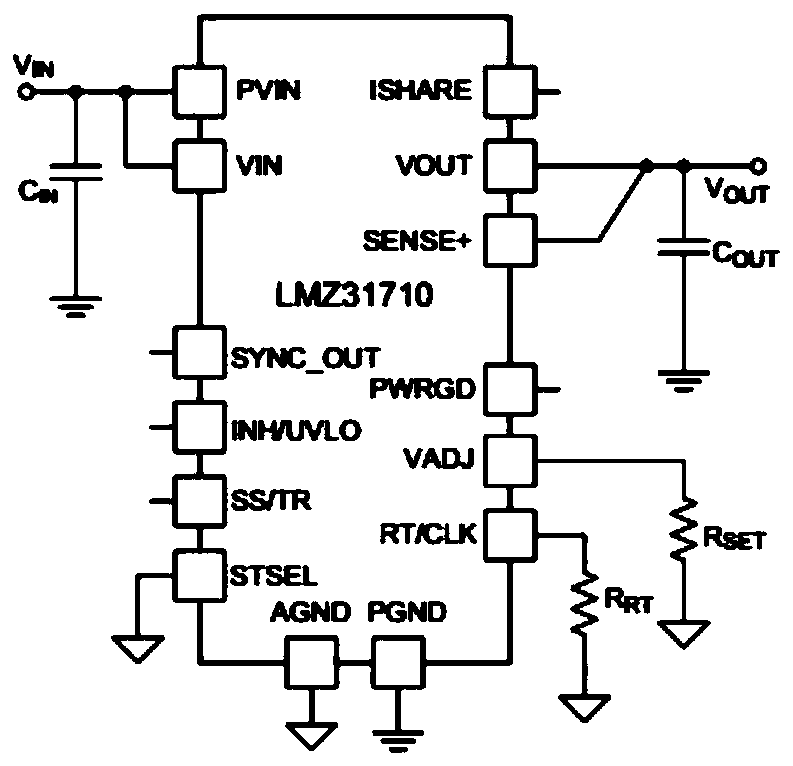
[0041] This embodiment is realized based on the power module LMZ31710, the first digitally controlled potentiometer AD5292-20 (1024 resolution / 20K resistance) and the second digitally controlled potentiometer AD5292-200 (1024 resolution / 200K resistance), and other types of similar product.

[0042] Since the standard power supply voltages of digital integrated circuits are generally 1.0V, 1.2V, 1.5V, 1.8V, 2.5V, 3.3V, 5.0V, etc., the output voltage range of the power supply module in this embodiment mainly covers ±10V of the above voltages. % Bias voltage range, the same method can be used to design for voltage values ​​not listed.

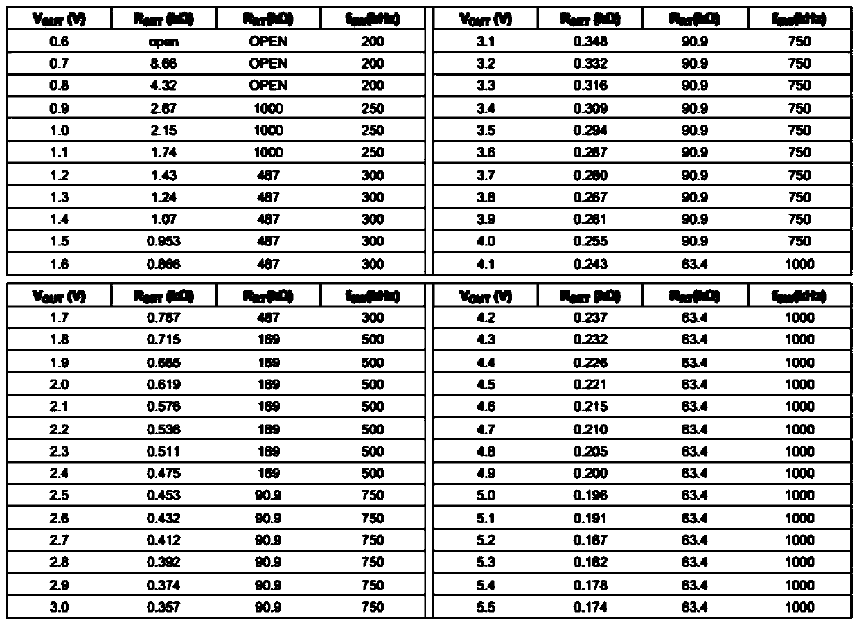
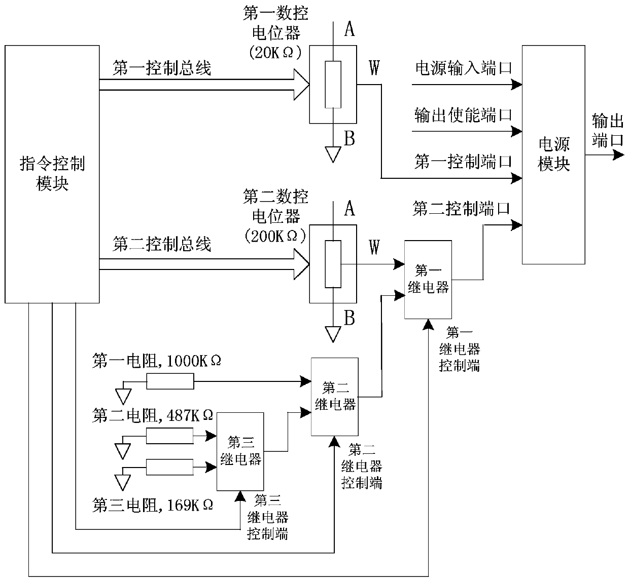
[0043] Table 1 lists in detail the voltage pull-off values ​​mainly covered by this embodiment, R SET with R RT It is the resistance value that needs to be connected to the first control terminal and the second control terminal of the power module; R1 / R2 / R3 are the switch states of the first / second / third relays respectively, open means that the ...


PUM


Abstract

The invention relates to a board-mode program-controlled voltage bias test circuit of a large-scale digital integrated circuit. The program-controlled voltage bias test circuit comprises a power supply module, a first numerical control potentiometer, a second numerical control potentiometer, a first relay, a second relay, a third relay, a first resistor, a second resistor, a third resistor and aninstruction control module, wherein a first control end of the power supply module is connected with an adjustable resistor end of the first numerical control potentiometer, a second control end of the power supply module is connected with an output end of the first relay, a first input end of the first relay is connected with an adjustable resistor end of the second numerical control potentiometer, and a first input end of the first relay is connected with an output end of the second relay. According to the invention, through cooperation of the power supply module, the numerical control potentiometer, the relay, the resistor and the instruction control module, automatic control of bias voltage in a large-scale digital circuit board mode bias test is realized, a large-size special instrument does not need to be carried, and thus the portability is better.

Description

technical field [0001] The invention relates to a board mode program-controlled voltage bias test circuit of a large-scale digital integrated circuit, which belongs to the field of integrated circuit tests. Background technique [0002] When performing reliability tests such as board-level electrical performance testing, verification, and burn-in of large-scale digital integrated circuits, it is often necessary to conduct voltage bias tests on the core, IO, PLL, and other dedicated power supply ports of the circuit. The bias voltage is generally in the manual About ±10% of the rated value. In the actual test, there are mainly three ways to supply power to the circuit: (1) through a special program-controlled power supply instrument; (2) through a power module with fixed voltage output, such as DC / DC, LDO, etc.; (3) through a power supply with variable voltage output module. The above methods have the following problems in actual use: [0003] (1) The main problem of using...

Claims


Application Information

Patent Timeline
Patent Type & Authority Applications(China)
IPC IPC(8): G01R31/30G01R31/317G01R31/3173
CPCG01R31/3004G01R31/317G01R31/3173
Inventor 王贺张大宇汪悦张红旗张松李剑焘崔华楠杨彦朝庄仲吉美宁
Owner CHINA ACADEMY OF SPACE TECHNOLOGY
Why Eureka
Try Eureka