
Magnetic vibration thermal conductor used for magnetic vibration thermal treatment pad and magnetic vibration thermal treatment pad

A technology of magnetic vibration heating and therapeutic pads, which is applied in the field of medical devices, can solve the problems of increased magnetic induction intensity, difficulty in realizing production cost control, and high additional production costs, etc., to achieve increased magnetic induction intensity of magnetic field, easy symmetrical distribution, and treatment uniform effect

Pending Publication Date: 2020-03-24
GUANGZHOU YIHE MEDICAL TECH DEV
View PDF0 Cites 0 Cited by
  • Summary
  • Abstract
  • Description
  • Claims
  • Application Information

AI Technical Summary

Problems solved by technology

[0007] In order to solve the problem that the magnetic induction intensity of the treatment contact surface of the magnetic vibration thermal treatment pad is ensured by increasing the number of coil turns wound on the magnetic vibration thermal conductor, the difficulty of a large and effective increase in the magnetic induction intensity is large and increases. The extra production cost caused by the number of coil turns is high, and it is difficult to realize the technical problem of controlling the production cost in large-scale industrial production. The present invention provides a magnetic vibration thermal conductor and Magnetic Vibration Thermal Therapy Pad

Method used


Image

  • Magnetic vibration thermal conductor used for magnetic vibration thermal treatment pad and magnetic vibration thermal treatment pad
  • Magnetic vibration thermal conductor used for magnetic vibration thermal treatment pad and magnetic vibration thermal treatment pad
  • Magnetic vibration thermal conductor used for magnetic vibration thermal treatment pad and magnetic vibration thermal treatment pad

Examples


Embodiment 1

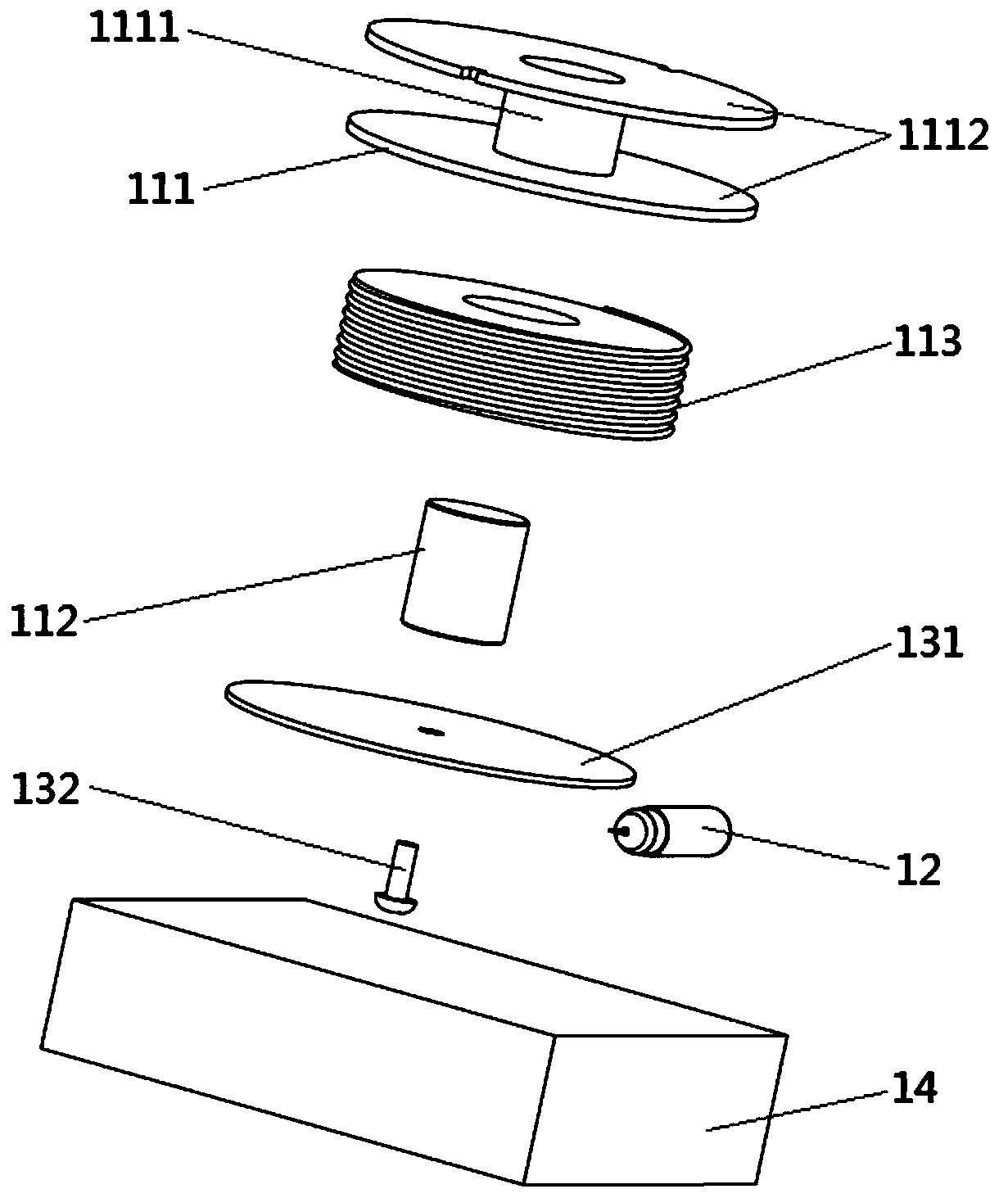
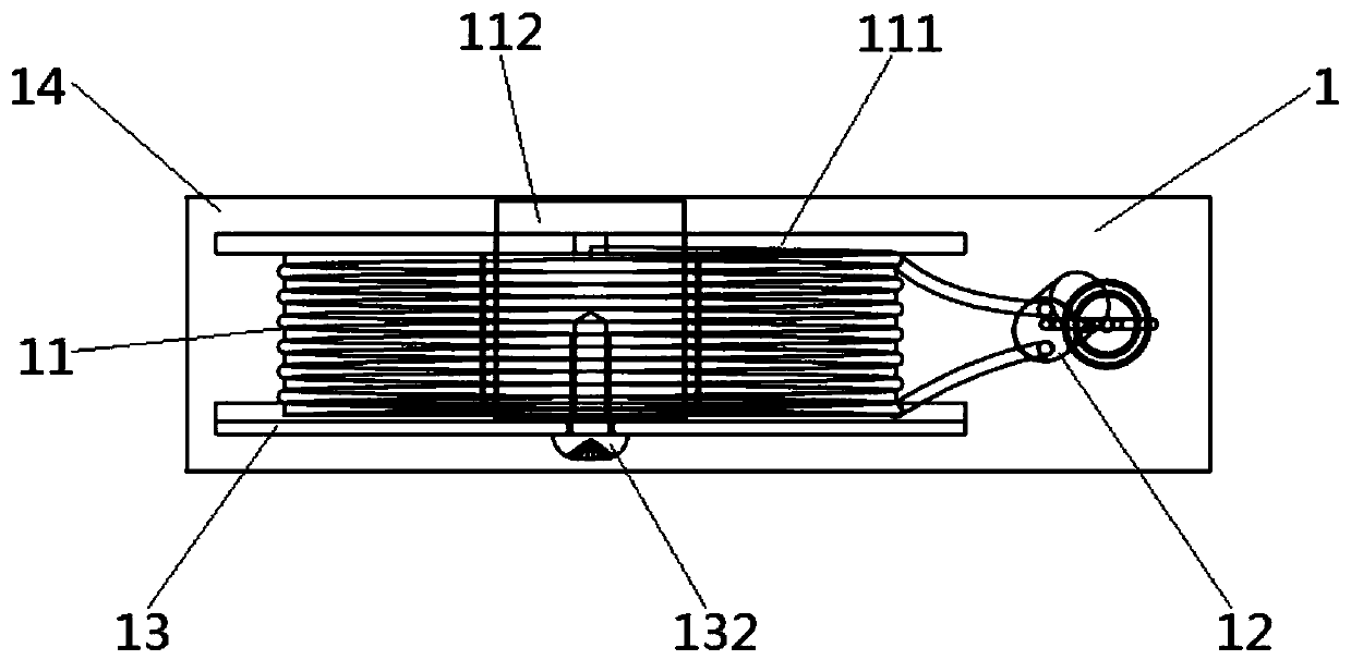
[0036] Such as Figure 1~5As shown, a magnetic vibration heat conduction 1 and a "mountain" shaped magnetic vibration heat treatment pad 2 made of the magnetic vibration heat conduction 1, the magnetic vibration heat conduction 1 includes a coil group 113 pieces 11 and Vibration motor 12, described coil group 113 parts 11 comprise I-shaped skeleton 111, magnetic rod 112 and coil group 113, described I-shaped skeleton 111 comprises the fixed plate 1112 of hollow winding area 1111 and both sides, and described magnetic rod 112 is fixed Inside the hollow winding area 1111, the coil group 113 is fixed outside the hollow winding area 1111 and inside the fixing plate 1112;

[0037] One side of the I-shaped frame 111 is provided with a magnetic attracting mechanism 13, and the magnetic attracting mechanism 13 includes an attracting magnet piece 131 and a fixing screw 132, and the attracting magnet piece 131 is close to the fixing plate 1112 and cooperates with the fixing screw 132 m...

Embodiment 2

[0047] Such as Figure 1~4 and Figure 6 As shown, a magnetic vibration heat conduction 1 and a "T" shaped magnetic vibration heat treatment pad 2 made of the magnetic vibration heat conduction 1, the magnetic vibration heat conduction 1 includes a coil group 113 pieces 11 and Vibration motor 12, described coil group 113 parts 11 comprise I-shaped skeleton 111, magnetic rod 112 and coil group 113, described I-shaped skeleton 111 comprises the fixed plate 1112 of hollow winding area 1111 and both sides, and described magnetic rod 112 is fixed Inside the hollow winding area 1111, the coil group 113 is fixed outside the hollow winding area 1111 and inside the fixing plate 1112;

[0048] One side of the I-shaped frame 111 is provided with a magnetic attracting mechanism 13, and the magnetic attracting mechanism 13 includes an attracting magnet piece 131 and a fixing screw 132, and the attracting magnet piece 131 is close to the fixing plate 1112 and cooperates with the fixing scr...

Embodiment 3

[0058] Such as Figure 1~5 As shown, a magnetic vibration heat conduction 1 and a rectangular magnetic vibration heat treatment pad 2 made of the magnetic vibration heat conduction 1, the magnetic vibration heat conduction 1 includes a coil group 113 parts 11 and a vibration motor 12 , the coil set 113 piece 11 includes an I-shaped frame 111, a magnetic bar 112 and a coil set 113, and the I-shaped frame 111 includes a hollow winding area 1111 and fixing plates 1112 on both sides, and the magnetic bar 112 is fixed on the Inside the hollow winding area 1111, the coil group 113 is fixed outside the hollow winding area 1111 and inside the fixing plate 1112;

[0059] One side of the I-shaped frame 111 is provided with a magnetic attracting mechanism 13, and the magnetic attracting mechanism 13 includes an attracting magnet piece 131 and a fixing screw 132, and the attracting magnet piece 131 is close to the fixing plate 1112 and cooperates with the fixing screw 132 mutually fixed ...


PUM


Abstract

The invention relates to a magnetic vibration thermal conductor and a magnetic vibration thermal treatment pad manufactured based on the magnetic vibration thermal conductor. The magnetic vibration thermal conductor includes a coil component and a vibration motor, the coil component includes an I-shaped framework, a magnetic rod and a coil group, the I-shaped framework includes a hollow winding area and fixing plates on two sides, the magnetic rod is fixed on the inner side of the hollow winding area, and the coil group is located on the inner sides of the fixing plates; a magnetism guide mechanism is arranged on one side of the I-shaped framework, the magnetism guide mechanism includes a magnetism guide iron sheet and a fixing screw, and the magnetism guide iron sheet is closely attachedto one fixing plate and cooperates with the fixing screw for being mutually fixed with the magnetic rod; and the coil component and the vibration motor are fixed in a filling and sealing element. Themagnetic vibration thermal treatment pad includes a pad body and a plurality of magnetic vibration thermal conductors, and the magnetic vibration thermal conductors are uniformly distributed and fixedto the pad body. According to the magnetic vibration thermal conductor, the magnetism guide mechanism is arranged, so that the magnetic induction intensity can be improved, the requirement for required turns per coil can be reduced, and high production costs can be avoided.

Description

technical field [0001] The invention relates to the technical field of medical devices, in particular to a magnetic vibration thermal conductor used for a magnetic vibration thermal therapy pad and a magnetic vibration thermal therapeutic pad. Background technique [0002] The magnetic vibrating heat therapy instrument is suitable for the auxiliary treatment of chronic soft tissue injury and neck, shoulder, waist and leg pain. It is based on computer processing and combines three physical factors of magnetic field, vibration and heat. A comprehensive treatment instrument that combines magnetic therapy, vibration therapy and thermal therapy with magnetic vibration thermal conductors. [0003] After the magnetic vibration thermal conduction sub-coil is energized, on the one hand, an alternating magnetic field is generated for magnetic therapy. The magnetic field can change the size and direction of the human body's biological current, and generate a weak induced eddy current,...

Claims


Application Information

Patent Timeline
Patent Type & Authority Applications(China)
IPC IPC(8): A61N2/04A61H23/02
CPCA61N2/008A61N2/002A61N2/02A61H23/02A61H2201/10
Inventor 马振尉戚锦磊邓浮池李威谕
Owner GUANGZHOU YIHE MEDICAL TECH DEV
Learn More