
Surface grinding device with cooling structure for machining manual wrench

A technology of cooling structure and cooling mechanism, applied in the field of manual wrench, which can solve the problems of overheating, inconvenient grinding and cutting operations, and inconvenient regulation, etc., and achieve the effect of increasing the contact area, improving the cooling effect, and increasing the cooling effect

Inactive Publication Date: 2020-03-17
东莞市史雷帝三维数控科技有限公司
View PDF0 Cites 3 Cited by
  • Summary
  • Abstract
  • Description
  • Claims
  • Application Information

AI Technical Summary

Problems solved by technology

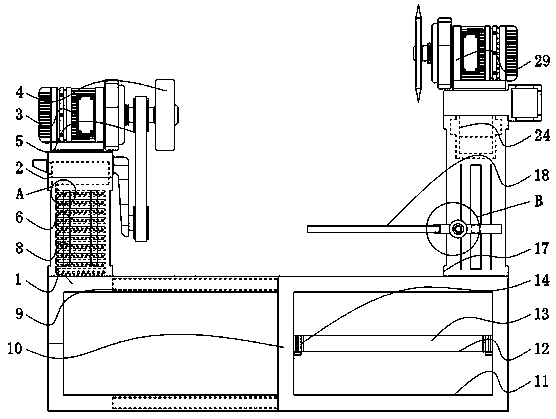
[0004] The object of the present invention is to provide a surface grinding device with a cooling structure for the processing of a manual wrench, so as to solve the problem that the existing grinding device proposed in the background technology has better grinding and grinding mechanisms because it is not installed. As a result, the operation of the device body is not convenient enough for grinding and cutting. At the same time, the main body generally has the problem of excessively high temperature during processing, and the main body also has the problem of inconvenient regulation when it is installed and used. The problem

Method used


Image

  • Surface grinding device with cooling structure for machining manual wrench
  • Surface grinding device with cooling structure for machining manual wrench
  • Surface grinding device with cooling structure for machining manual wrench

Examples


Embodiment Construction

[0027] The following will clearly and completely describe the technical solutions in the embodiments of the present invention with reference to the accompanying drawings in the embodiments of the present invention. Obviously, the described embodiments are only some, not all, embodiments of the present invention.

[0028] In the description of the present invention, unless otherwise stated, the meaning of "plurality" is two or more; the terms "upper", "lower", "left", "right", "inner", "outer" , "front end", "rear end", "head", "tail", etc. indicate the orientation or positional relationship based on the orientation or positional relationship shown in the drawings, and are only for the convenience of describing the present invention and simplifying the description, rather than Indicates or implies that the device or element referred to must have a particular orientation, be constructed and operate in a particular orientation, and therefore should not be construed as limiting the...


PUM


Abstract

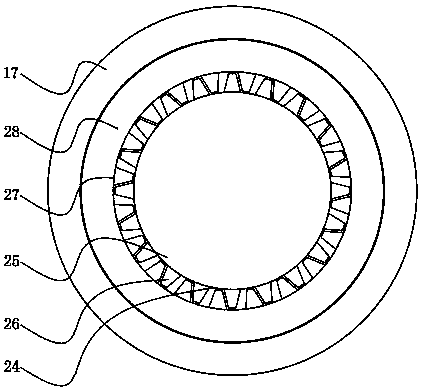
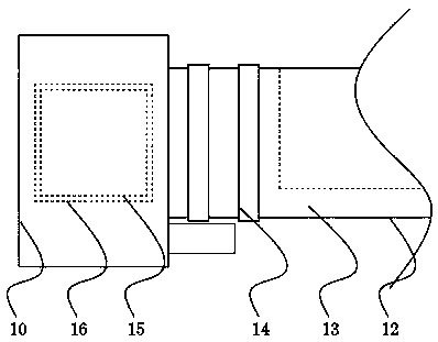
The invention relates to a surface grinding device with a cooling structure for machining a manual wrench. The surface grinding device comprises a device body and a cooling mechanism. A lateral side base is arranged on the top of the left end of the device body. A transmission mechanism is arranged at the top end of the lateral side base. A grinding belt is arranged on the right side of the top end of the transmission mechanism. A grinding wheel is placed at the right end of the grinding belt. The cooling mechanism is located in the middle of the lateral side base. A movable strip is arrangedin the right end of the device body. The surface grinding device with the cooling structure for machining the manual wrench has the advantages that by means of a cooling pipeline of an S-shaped structure, cooling liquid can be conveniently carried, the contact area of the cooling pipeline and the cooling liquid can be conveniently increased due to the S-shaped structure design, and the cooling effect is improved; and moreover, the cooling effect can be further improved through cooling of air holes, the device body can be cooled when the device body performs transmission, grinding and other machining operations through the transmission mechanism, and therefore the cooling and protecting effect of the surface grinding device is improved.

Description

technical field [0001] The invention relates to the technical field of manual wrenches, in particular to a surface grinding device with a cooling structure for processing manual wrenches. Background technique [0002] Manual wrench is also called ordinary wrench. It is mainly used in ordinary life and work. Its use is relatively simple. It is mainly divided into single-head wrench, double-head wrench, adjustable wrench, ring wrench, multi-purpose wrench, percussion wrench, socket wrench , socket driver, torque wrench, torque wrench, and it can generally be processed with a grinding device. [0003] Because the existing grinding device is not equipped with better grinding and grinding mechanisms, the operation of the device body is not convenient enough for grinding and cutting, and the main body generally also has problems when processing. The problem of excessive temperature is generated, and the main body also has the problem of inconvenient regulation when it is installe...

Claims


Application Information

Patent Timeline
IPC IPC(8): B24B19/00B24B55/02B24B41/06B24B27/00B24B21/00B23P23/04
CPCB23P23/04B24B19/00B24B21/006B24B21/008B24B27/0076B24B41/06B24B55/02
Inventor 黄红梅马浩鹏
Owner 东莞市史雷帝三维数控科技有限公司
Learn More