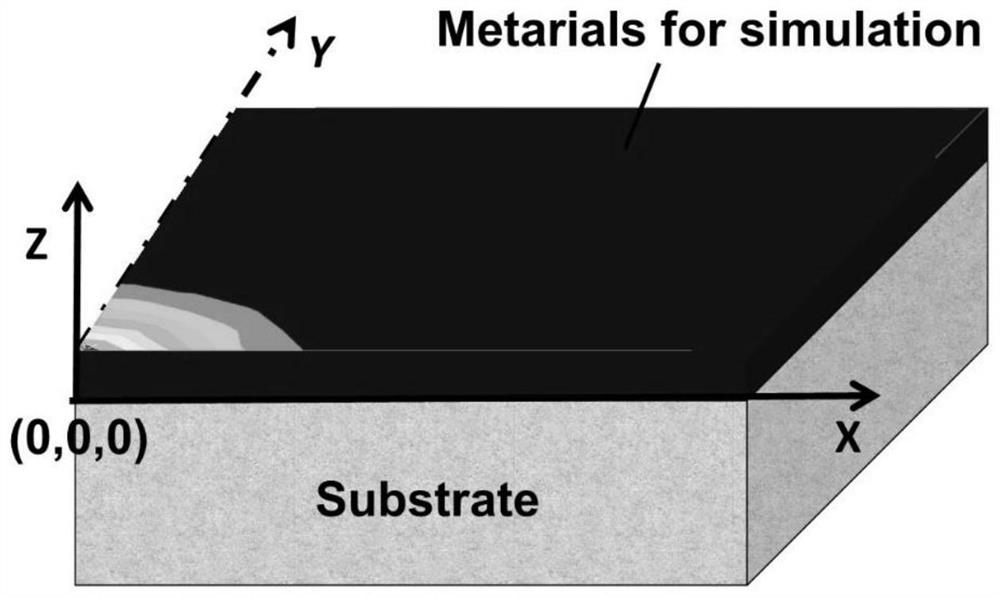
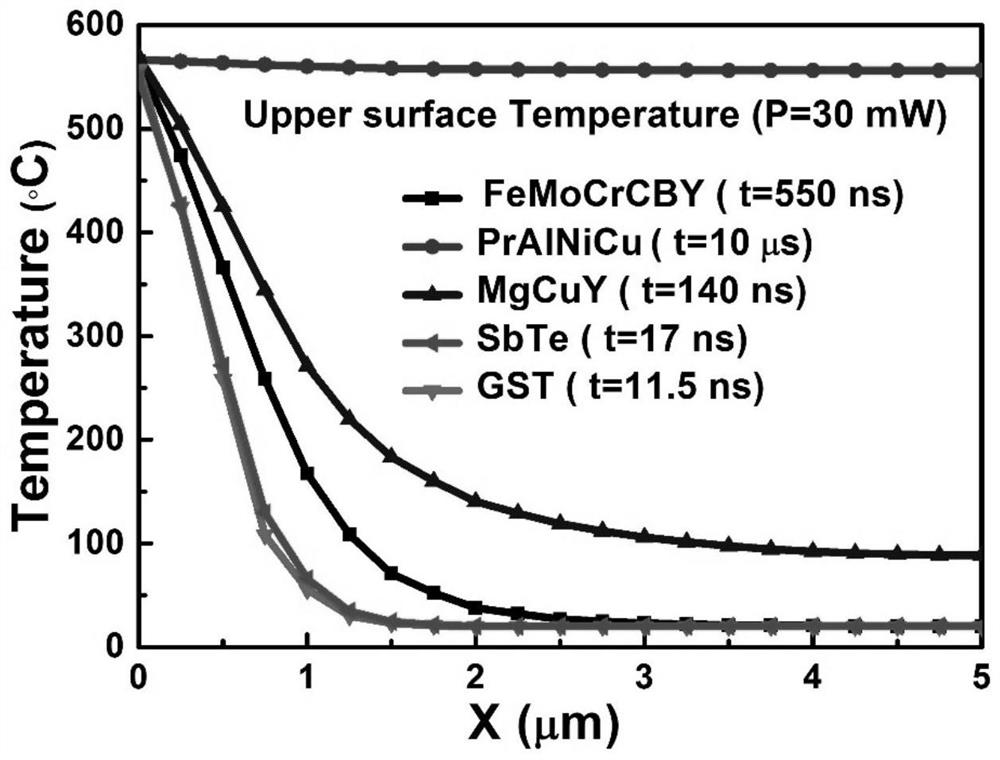
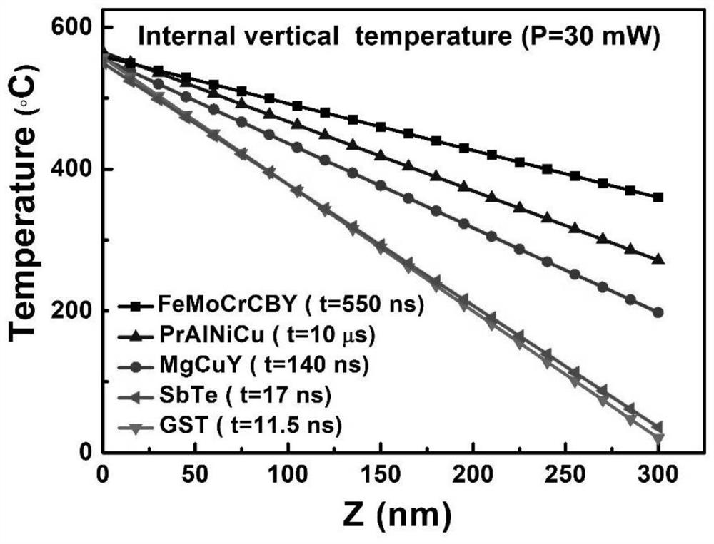
A kind of femocrcby phase change film, preparation method and 3D simulation transient heat distribution method
A transient thermal, 3D technology, applied in design optimization/simulation, calculation, electrical components, etc., to achieve the effect of high resolution, high resolution and simplified application
- Summary
- Abstract
- Description
- Claims
- Application Information
AI Technical Summary
Problems solved by technology
Method used
Image
Examples
preparation example Construction
[0033] A kind of preparation method of FeMoCrCBY phase-change film of the present invention, comprises the steps:
[0034] Grinding the FeMoCrCBY target to remove the surface oxide layer;
[0035] Then place the FeMoCrCBY target on the DC sputtering target holder of the sputtering chamber, and place the quartz glass substrate to be sputtered on the sample tray of the sputtering chamber;
[0036] Vacuum the sputtering chamber, the vacuum degree is between 1*10-4 Pa~1*10-5Pa;
[0037] Set the condition parameters in the sputtering process, including argon pressure, argon pressure flow rate, sputtering power and target distance, and prepare FeMoCrCBY film by sputtering inside the sputtering chamber through DC magnetron, and the sputtering power is 40W~100W, The flow rate of the argon pressure is 10sccm-60sccm, the sputtering argon pressure is 0.3Pa-0.7Pa, and the target distance is 60cm-120cm.
[0038]Specifically, the sputtering power is set to 40W to 100W. Since the FeMoCrCBY...
Embodiment 1
[0049] A kind of preparation method of FeMoCrCBY phase-change thin film of the present invention, in the present embodiment, selects Fe48Mo14Cr15C15B6Y2 as phase-change material, and its step of preparing phase-change thin film operates as follows:
[0050] S1: Grinding the Fe48Mo14Cr15C15B6Y2 target to remove the surface oxide layer;
[0051] S2: Place the Fe48Mo14Cr15C15B6Y2 target on the DC sputtering target holder of the sputtering chamber, and place the sample to be sputtered on the sample tray of the sputtering chamber;
[0052] S3: Vacuumize the sputtering chamber at 1*10-5Pa;
[0053] S4: Set the condition parameters in the sputtering process, including argon pressure, argon pressure flow rate, sputtering power and target distance, and prepare a Fe48Mo14Cr15C15B6Y2 film in the sputtering chamber by DC magnetron, and the sputtering power is 100W, The flow rate of argon pressure is 30 sccm, the sputtering argon pressure is 0.5 Pa, and the distance between targets is 60 ...
Embodiment 2
[0061] A kind of preparation method of FeMoCrCBY phase-change thin film of the present invention, in the present embodiment, selects Fe48Mo14Cr15C15B6Y2 as phase-change material, and its step of preparing phase-change thin film operates as follows:
[0062] S1: Grinding the Fe48Mo14Cr15C15B6Y2 target to remove the surface oxide layer;
[0063] S2: Place the Fe48Mo14Cr15C15B6Y2 target on the DC sputtering target holder of the sputtering chamber, and place the sample to be sputtered on the sample tray of the sputtering chamber;
[0064] S3: Vacuum the sputtering chamber, the vacuum is 1*10-4Pa;
[0065] S4: Set the condition parameters in the sputtering process, including argon pressure, argon pressure flow rate, sputtering power and target distance, and prepare Fe48Mo14Cr15C15B6Y2 film by sputtering in the sputtering cavity through DC magnetron, and the sputtering power is 40W, The flow rate of the argon pressure is 10 sccm, the sputtering argon pressure is 0.7 Pa, and the tar...
PUM
| Property | Measurement | Unit |
|---|---|---|
| thickness | aaaaa | aaaaa |
| thickness | aaaaa | aaaaa |
| thickness | aaaaa | aaaaa |
Abstract
Description
Claims
Application Information
 - R&D
- Intellectual Property
- Life Sciences
- Materials
- Tech Scout
- Unparalleled Data Quality
- Higher Quality Content
- 60% Fewer Hallucinations
Browse by: Latest US Patents, China's latest patents, Technical Efficacy Thesaurus, Application Domain, Technology Topic, Popular Technical Reports.
© 2025 PatSnap. All rights reserved.Legal|Privacy policy|Modern Slavery Act Transparency Statement|Sitemap|About US| Contact US: help@patsnap.com


