
Method and network device for measuring delay

A technology of network equipment and delay

Active Publication Date: 2022-01-18
HUAWEI TECH CO LTD
View PDF14 Cites 0 Cited by
  • Summary
  • Abstract
  • Description
  • Claims
  • Application Information

AI Technical Summary

Problems solved by technology

As the number of cascaded devices increases, uncertain delays will accumulate, resulting in reduced communication efficiency

Method used


Image

  • Method and network device for measuring delay
  • Method and network device for measuring delay
  • Method and network device for measuring delay

Examples


Embodiment Construction

[0135] The technical solutions in the present application will be described below in conjunction with the drawings.

[0136] For a better understanding of the present embodiment method of measuring delay application of the embodiment, the first following some basic concepts will be briefly described.

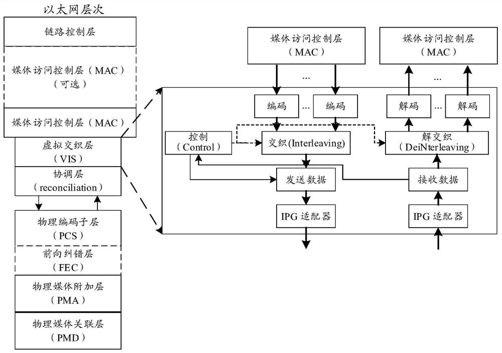
[0137] Reconciliation sublayer (reconciliation sub-layer, RS), its main function is to provide a mapping mechanism between a signal (media-independent interface, MII), and media access control layer (media access control, MAC) A media independent interface.

[0138] The MAC layer, its main function is responsible for the "0" physical layer, "1" bit stream formation framing, and error check by error check information frame tail.

[0139] MAC sublayer, its main function is to add a physical address of the target computer to the data frame when the data frame to the MAC layer of the terminal, it checks whether the address matches its own address, if the address in the frame does not ma...


PUM


Abstract

The present application provides a method for measuring time delay and a network device. The method includes: a first network device receives a first service flow; the first network device determines a first A time delay value, where the first time delay value is a time difference between the first moment and the second moment when the first measurement code block is detected in the first network device. Based on the above technical solution, the network device can determine the delay value of the service flow by measuring the delay value of the measurement code block in the service flow.

Description

Technical field [0001] The present application relates to the field of information technology, and more particularly, to a method and a network delay measurement devices. Background technique [0002] Interleaving virtual sub-layer (virtual interleaving sub-layer, VIS) technology in itself is a time division multiplexing media access control layer (media access control, MAC) or less, the MAC layer below the slotted channel. After slotted, can be transmitted using the low-speed industrial Ethernet service slotted channel. But slotted bring common way delay uncertainties that business relations random arrival time and transmission time slots, resulting in service delays uncertain. [0003] When the service is mapped to the VIS in the slot, export business mapping and caching will delay the introduction of uncertainty. With the increase in the number of cascaded devices, uncertainty will delay cumulative, resulting in lowering the communication efficiency. Inventive content [0004...

Claims


Application Information

Patent Timeline
Patent Type & Authority Patents(China)
IPC IPC(8): H04L43/0852H04L43/08
CPCH04L43/0852H04L43/08H04L43/026H04L43/0858H04L41/142H04L1/0057H04L47/283H04L12/40136
Inventor 汪仁磊楼喆查敏朱志刚
Owner HUAWEI TECH CO LTD
Learn More