
Electrostatic dust removal device

An electrostatic precipitator and dust-collecting board technology, which is applied in the field of electrostatic precipitator, can solve the problems of affecting the electrostatic field of the discharge electrode and the dust-collecting board, affecting the adsorption effect of the dust-collecting board, and reducing the dust-removing ability of the electrostatic precipitator equipment.

Inactive Publication Date: 2020-02-28
国能珠海港务有限公司
View PDF5 Cites 1 Cited by
  • Summary
  • Abstract
  • Description
  • Claims
  • Application Information

AI Technical Summary

Problems solved by technology

[0003] However, during the operation of the traditional electrostatic precipitator, when the dust concentration is high, the dust particles on the dust collection plate are saturated, which greatly reduces the dust removal ability of the electrostatic precipitator. At present, for the electrostatic precipitator to realize automatic cleaning of the dust collection plate, a large Most of them realize automatic cleaning by water spray integrated board, but in the actual process, when water spray technology is used to wash the dust collection plate, there are many problems, such as the dust removal component is relatively wet after water spray, which affects the generation between the discharge electrode and the dust collection plate. Electrostatic field, thus affecting the adsorption effect of the dust collection plate

Method used


Image

  • Electrostatic dust removal device

Examples


Embodiment 1

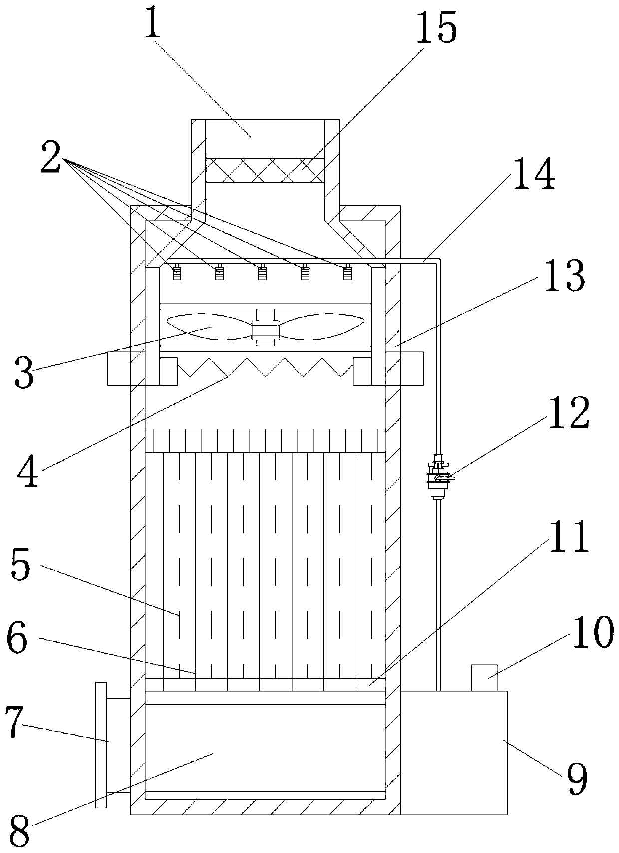
[0028] refer to figure 1 , an electrostatic precipitator provided by the present invention, comprising: an outer box body 13, an air inlet pipe 1 and an air outlet pipe 7, the outer box body 13 is in a barrel-shaped structure, and one end of the air inlet pipe 1 is installed on the top of the outer box body 13 and extends To the inside of the outer box body 13, an activated carbon filter screen 15 is provided in the air intake pipe 1 to initially filter the gas in the air intake pipe 1, and the end of the air intake pipe 1 pierced to the inside of the outer box body 13 is provided with a funnel-shaped mouth. The diameter of the opening is the same as the inner diameter of the outer box 13, so that the filtered gas enters the outer box 13; the upper part of the inner wall of the outer box 13 is provided with a fan 3, and the bottom of the fan 3 is provided with a heating wire 4, and the two ends of the heating wire 4 are connected To the two ends of the output line of the trans...


PUM


Abstract

The invention discloses an electrostatic dust removal device, which includes an outer box body, an air inlet pipe and an air outlet pipe. The outer box body has a barrel-shaped structure. By the abovetechnical scheme, after a fan guides dust into the air inlet pipe, the dust is preliminarily filtered by an activated carbon filter screen and then enters the outer box body; an electrostatic field is generated between a discharge electrode and a dust collecting plate, and the preliminarily filtered dust particles are charged and adsorbed onto the dust collecting plate; a water pump is turned on,an atomizing nozzle sprays atomized water vapor to adsorb the dust particles into the electrostatic field generated between the discharge electrode and the dust collecting plate, and the atomized water with the dust particles flows into a sewage discharge tank under the influence of gravity; when the dust collecting plate is humid, the water pump is turned off, and dry hot air is generated through the fan and an electric heating wire, so as to quickly dry the dust collecting plate. Through the embodiment of the invention, dust particles can be adsorbed, and the electrostatic field generated between the discharge electrode and the dust collecting plate is not affected, and a cleaning effect on the dust collecting plate is also achieved; and a water film can be formed on the dust collectingplate, the adsorption effect of the dust collecting plate is enhanced, and the dust collecting plate that is too humid also can be dried.

Description

technical field [0001] The invention relates to the field of electrostatic dust removal, in particular to an electrostatic dust removal device. Background technique [0002] Electrostatic dust removal is a kind of gas dust removal method. The dust-containing gas is electrically separated when it passes through a high-voltage electrostatic field. After the dust particles are combined with negative ions and charged with negative charges, they tend to discharge and deposit on the surface of the anode. They are used to purify gases in metallurgy, chemical and other industries. Or recover useful dust particles, use the electrostatic field to ionize the gas so that the dust particles are charged and adsorbed to the electrode. In the strong electric field, the air molecules are ionized into positive ions and electrons, and the electrons encounter dust particles in the process of rushing to the positive electrode. , so that the dust particles are negatively charged and adsorbed to t...

Claims


Application Information

Patent Timeline
IPC IPC(8): B03C3/16B03C3/53B03C3/011B03C3/014B03C3/34F26B21/00
CPCB03C3/011B03C3/014B03C3/16B03C3/34B03C3/53F26B21/001
Inventor 许国墩陈翼飞胡跃
Owner 国能珠海港务有限公司
Learn More