
A Highly Efficient Plasma Gas-Liquid Discharge System

A plasma and gas technology, applied in the direction of plasma, electrical components, etc., can solve the problem of no plasma energy utilization, etc., to achieve the effect of easy disassembly and maintenance, enhanced processing efficiency, and good support

Active Publication Date: 2021-01-15
锦州高新生产力促进中心有限公司
View PDF11 Cites 0 Cited by
  • Summary
  • Abstract
  • Description
  • Claims
  • Application Information

AI Technical Summary

Problems solved by technology

Most of the traditional low-temperature plasma technology uses plasma-activated gas in the application process, and does not really utilize the energy of high-energy electrons in the plasma.

Method used


Image

  • A Highly Efficient Plasma Gas-Liquid Discharge System
  • A Highly Efficient Plasma Gas-Liquid Discharge System
  • A Highly Efficient Plasma Gas-Liquid Discharge System

Examples


Embodiment 1

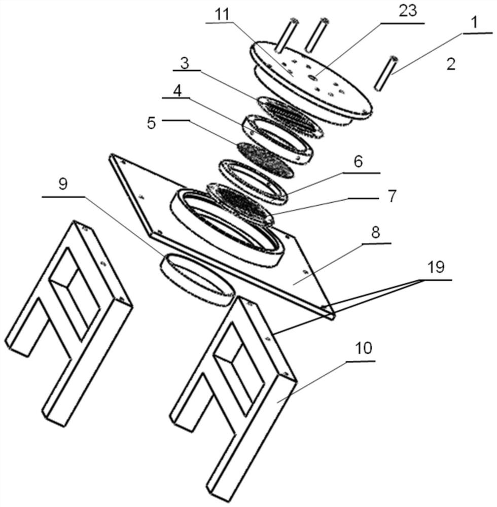
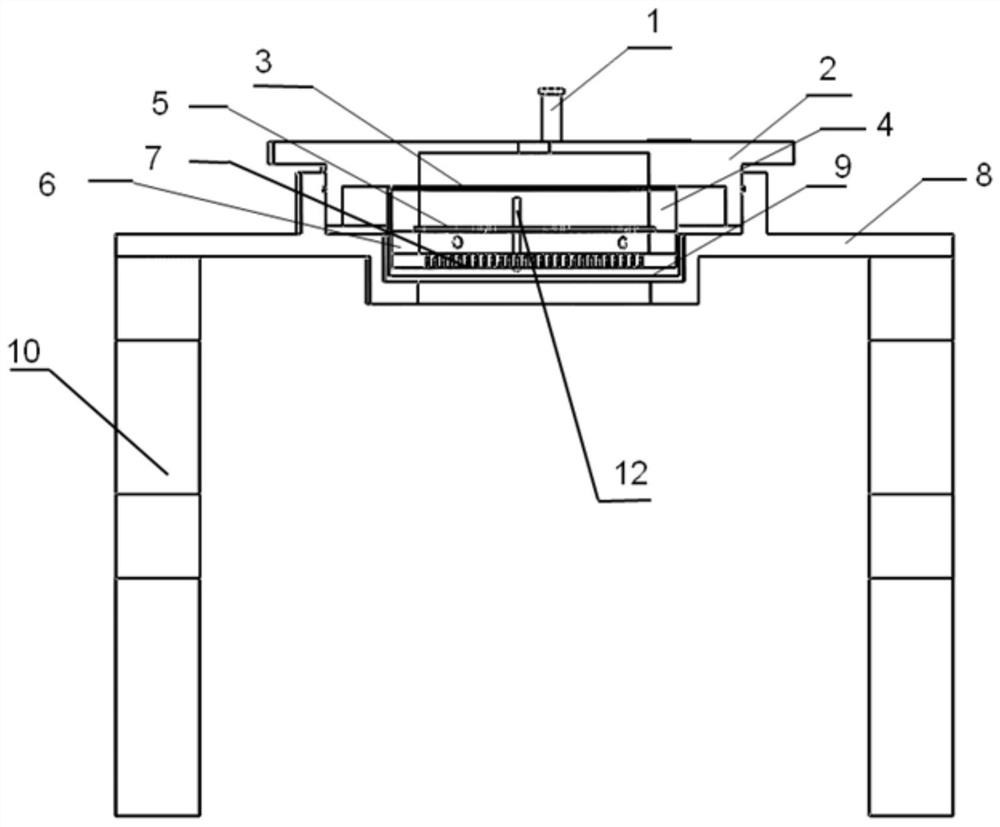
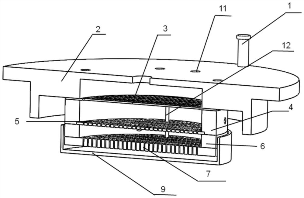
[0075] Such as Figure 1 to Figure 15 As shown, a high-efficiency plasma gas-liquid discharge system includes: a fixed plate I2 arranged sequentially from top to bottom, a dielectric plate I3 with long strip-shaped through holes (this embodiment is referred to as the dielectric plate I3), and a flat dielectric plate Plate II5 (abbreviated as medium plate II5 in this embodiment), flat medium plate III7 (abbreviated as medium plate III7 in this embodiment), medium dish 9, fixed plate II8, fixed plate I2 connected with medium plate I3, The gasket I4, the dielectric plate II5, the gasket II6, and the dielectric plate III7 are connected in sequence, and the dielectric plate II5 is located between the gasket I4 and the gasket II6. The center of the fixed plate II8 is provided with a medium plate 9, and the medium plate 9 is located between the medium plate III7 and the fixed plate II8; the fixed plate I2 is connected with the medium plate I1, the washer I4, the medium plate II5, Ga...

Embodiment 2

[0078] Such as Figure 1 to Figure 18As shown, a high-efficiency plasma gas-liquid discharge system includes: a fixed plate I2 arranged in sequence from top to bottom, a dielectric plate I13 with a circular through hole (this embodiment is referred to as the dielectric plate I13), and a dielectric plate I13 with an integrated structure. Plate II14 (abbreviated as medium plate II14 in this embodiment), medium plate III15 with boss structure (abbreviated as medium plate III15 in this embodiment), medium plate 9, fixed plate II8, and medium plate II14 with integrated structure is a gasket Ⅰ4, gasket Ⅱ6 and flat dielectric plate II constitute an integrated structure, and the flat dielectric plate Ⅱ and dielectric plate Ⅱ5 are located between gasket Ⅰ4 and gasket Ⅱ6. The fixed plate I2 is sequentially connected with the medium plate I3, the washer I4, the medium plate II5, the washer II6 and the medium plate III7 through the set screw 11. The center of the fixed plate II8 is provi...


PUM

PropertyMeasurementUnit
heightaaaaaaaaaa
heightaaaaaaaaaa
thicknessaaaaaaaaaa

Abstract

The invention discloses a high-efficiency plasma gas-liquid discharge system, comprising: a fixed plate I, a medium plate I, a medium plate II, a medium plate III, a medium dish, and a fixed plate II arranged in sequence from top to bottom; Plate I is sequentially connected with dielectric plate I, gasket I, gasket II, and dielectric plate III through fixing screws; the high-voltage electrode assembly is sequentially inserted into dielectric plate II and dielectric plate III through the through hole I opened by dielectric plate I; the dielectric plate II has a through hole II, and the medium plate III has a through hole III; the center of the fixed plate II is provided with a medium plate, and the medium plate is located between the medium plate III and the fixed plate II; the fixed plate I passes through The height adjustment screw is connected with the medium plate III, and the height adjustment screw is used to adjust the distance between the lower surface of the medium plate III and the upper surface of the medium dish. The invention can use plasma to directly process liquid, greatly enhances plasma processing efficiency, works stably, and is convenient for disassembly and maintenance.

Description

technical field [0001] The invention mainly relates to a plasma gas-liquid discharge system capable of directly discharging liquid. Background technique [0002] At present, with the continuous improvement of people's living standards, people's requirements for food safety are getting higher and higher, and they are paying more and more attention to issues such as pesticide residues on food surfaces and water source pollution. Low-temperature plasma technology has been widely used in the fields of agriculture and environmental protection, mainly in the removal of pesticide residues and sewage treatment. Most of the traditional low-temperature plasma technology uses plasma-activated gas in the application process, and does not really utilize the energy of high-energy electrons in the plasma. Contents of the invention [0003] The object of the present invention is to provide a plasma gas-liquid discharge system that is fast and efficient, has a simple structure, is easy to...

Claims


Application Information

Patent Timeline
Patent Type & Authority Patents(China)
IPC IPC(8): H05H1/24
CPCH05H1/2406H05H2245/00
Inventor 刘东平席婷
Owner 锦州高新生产力促进中心有限公司
Learn More