
Surrounding rock mechanical parameter automatic testing system and method suitable for TBM

An automatic testing system and technology of mechanical parameters, applied in the direction of applying stable tension/pressure to test material strength, soil material testing, testing wear resistance, etc., can solve problems that affect tunneling, high test accuracy, and long time consumption, and achieve Strong timeliness, high degree of automation, guaranteed accuracy and authoritative effect

Active Publication Date: 2020-02-21
山东百廿慧通工程科技有限公司
View PDF7 Cites 12 Cited by
  • Summary
  • Abstract
  • Description
  • Claims
  • Application Information

AI Technical Summary

Problems solved by technology

[0005] 1. The coring work in the TBM environment requires downtime and maintenance time, which affects the excavation
[0006] 2. The process of drilling, coring, processing and testing takes a long time, and the obtained rock mass parameters lack timeliness, which cannot meet the fast and real-time actual needs of TBM excavation for parameters such as rock mass compressive strength and abrasiveness indicators.
[0013] 6. The testing accuracy required for rock abrasive index testing is high. How to complete high-precision testing in the strong vibration environment of TBM excavation

Method used


Image

  • Surrounding rock mechanical parameter automatic testing system and method suitable for TBM
  • Surrounding rock mechanical parameter automatic testing system and method suitable for TBM
  • Surrounding rock mechanical parameter automatic testing system and method suitable for TBM

Examples


Embodiment 1

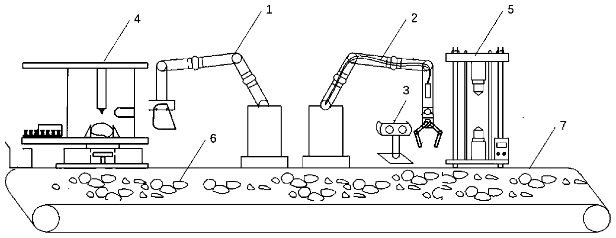
[0047] In one or more embodiments, an automatic testing system for surrounding rock mechanical parameters suitable for TBM is disclosed, referring to figure 1 , including: collection device 1, mechanical gripper 2, high-pressure nozzle 9, infrared depth binocular camera 3, compressive strength test bench 5, rock abrasiveness test bench 4.

[0048]During the TBM construction process, the rock slag 6 produced by the excavation of the TBM cutter head is transported out of the tunnel by the belt conveyor 7 . A collection device 1 , a mechanical gripper 2 , an infrared depth binocular camera 3 and a rock abrasiveness test bench 4 are arranged on one side of the conveying direction of the belt conveyor 7 .

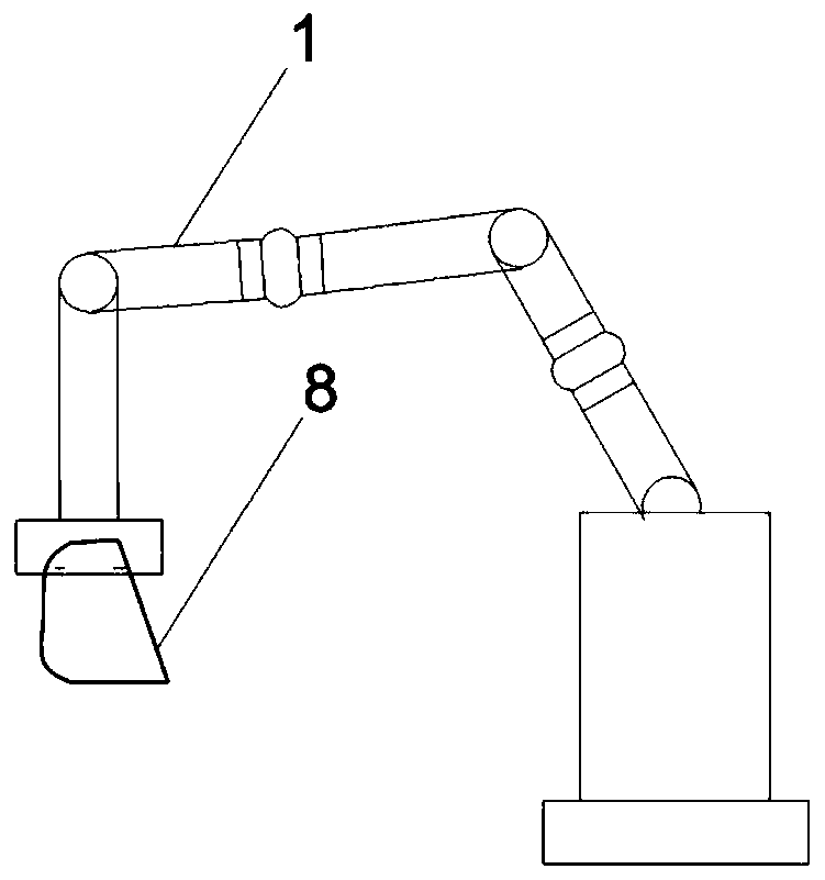
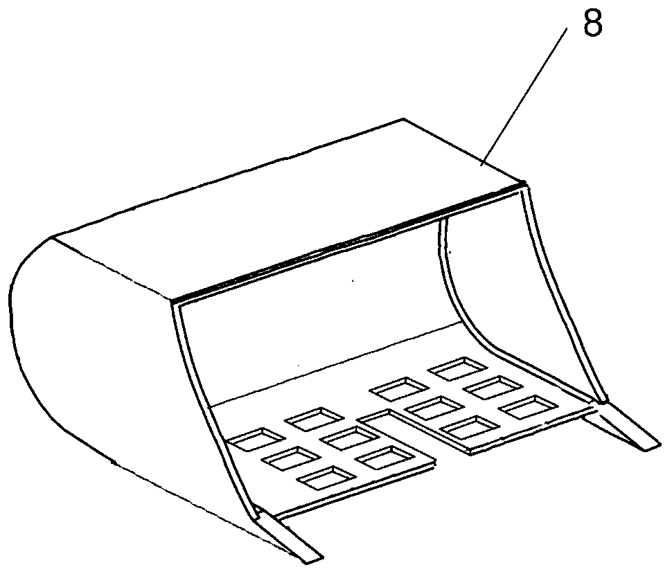
[0049] Among them, refer to figure 2 , The collecting device 1 is composed of a six-degree-of-freedom mechanical arm and a bucket 8, and can be placed beside the TBM belt conveyor 7. The robotic arm can translate in three mutually perpendicular coordinate systems of X-axis, Y...

Embodiment 2

[0069] In this embodiment, on the basis of Example 1, a compressive strength testing platform is added, referring to Figure 7 , The compressive strength test platform is composed of a platform support, an electro-hydraulic jack 19, two loading cones 18, and a program-controlled host 20. The platform bracket is supported by the upper platform, the test bench base, and the upper platform and the base with four steel columns.

[0070] The electro-hydraulic jack 19 drives two opposite loading cones 18 to move in opposite directions, and after the two loading cones 18 contact the rock slag, the current pressure of the rock slag is automatically recorded by the hydraulic sensor, and transmitted to the program-controlled host 20 . The two loading cones 18 are two movable loading cones 18, one up and one down, which can be displaced relative to each other. The tips of the two loading cones 18 are located on the same vertical line relative to the ground reference system. The program-...

Embodiment 3

[0073] On the basis of Embodiment 1 and Embodiment 2, this embodiment discloses a method for automatically testing surrounding rock mechanical parameters suitable for TBM, including the following working steps:

[0074] Collecting device 1 manipulator handles bucket 8 to contact the belt conveyor surface, stays for a short time on belt conveyor 7, and shovels out rock slag that moves on some belt conveyors 7. Since the shoveled rock slag will have a large number of rock slag fragments less than 30mm that do not meet the requirements of the compressive strength test, the bucket 8 is folded with the gap in the center of the bucket as the axis, so that the bucket surface is inclined, and the rock slag with a particle size of less than 30mm The slag fragments pass through the 30mm gap reserved in the middle of the bucket, while the rock slag with a particle size greater than 30mm is retained in the bucket 8 .

[0075] Specifically, the mechanical arm of the collecting device 1 fir...


PUM


Abstract

The invention discloses a surrounding rock mechanical parameter automatic testing system and a surrounding rock mechanical parameter automatic testing method suitable for a TBM. The surrounding rock mechanical parameter automatic testing system comprises a material collecting part, a grabbing part, a visual processing device and a rock abrasiveness testing device, wherein the material collecting part which can collect rock slag in a tunneling process of the TBM in real time; the grabbing part can grab arbitrary rock slag from the obtained rock slag; the visual processing device can perform three-dimensional imaging on the tested rock slag in an infrared distance measurement mode, calculates positions of loading points of an abrasiveness testing experiment, determines whether the tested rock slag meets requirements or not according to the distance between the loading points, if so, determines actual positions of the loading points, and determines that a region, meeting a set condition,on the surface of the rock slag serves as an action region of the abrasiveness testing experiment; and the rock abrasiveness testing device can automatically carry out abrasiveness testing on tested rock slag meeting the requirements. The surrounding rock mechanical parameter automatic testing system and the method have the advantages of being high in timeliness, high in automation degree, safe, economical and the like, effectively solve the problem that surrounding rock strength information of current TBM construction is difficult to obtain in real time, and provide real-time surrounding rockcondition information and a control parameter decision basis for TBM tunneling.

Description

technical field [0001] The invention relates to the technical field of testing surrounding rock mechanical parameters, in particular to an automatic testing system and method for surrounding rock mechanical parameters suitable for TBM. Background technique [0002] The statements in this section merely provide background information related to the present invention and do not necessarily constitute prior art. [0003] The TBM method is the mainstream method in the construction of deep and long tunnels. The construction has the advantages of fast excavation speed, low construction cost, small construction disturbance, and economical safety. However, TBM construction is extremely sensitive to rock mass conditions, and parameters such as uniaxial compressive strength and abrasiveness index (CAI) of surrounding rock seriously affect the construction efficiency and cost of TBM. In the construction section with high surrounding rock strength, the load required for TBM to break ro...

Claims


Application Information

Patent Timeline
Patent Type & Authority Applications(China)
IPC IPC(8): G01N3/56G01N3/12G01B11/24
CPCG01N3/56G01N3/12G01B11/24G01N2203/0003G01N2203/0048G01N2203/0676G01N2203/0682G01N33/24E21D9/003G01N3/565G01N3/08G01N35/02B25J9/1682B25J19/02G01N3/06G01N3/10G01N35/0099
Inventor 刘斌王瑞睿高博洋郭旭王亚旭赵光祖朱颜王滨
Owner 山东百廿慧通工程科技有限公司
Learn More