Tin bath for float glass forming process
A molding process and float glass technology, applied in glass manufacturing equipment, glass transportation equipment, manufacturing tools, etc., can solve problems such as lowering the temperature of tin liquid, intrusion of external air, process fluctuations, etc., to ensure surface quality, avoid intrusion, The effect of improving transmission efficiency
- Summary
- Abstract
- Description
- Claims
- Application Information
AI Technical Summary
Problems solved by technology
Method used
Image
Examples
Embodiment 1
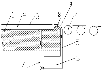
[0022] Such as figure 1 In the tin bath shown in the float glass forming process, a semicircular or arc-shaped tin bath edge 8 is arranged at the end of the tin bath outlet, and a diversion groove 9 is arranged outside the edge 8, and the diversion groove 9 passes through the The diversion pipe 5 is connected to the recovery tank 6 at the bottom, and the recovery tank 6 is connected to the tin bath through the circulation pump and the liquid supply pipe 7. The edge 8 is lower than the surface of the tin liquid 2, and the tin liquid 2 flows out along the edge through the diversion tank 9 And the guide pipe 5 flows into the bottom recovery tank 6, and then the tin liquid is sent from the liquid supply pipe 7 to the tank in front of the mouth 8 through the circulation pump to form a circulation.
[0023] The tin bath device includes tin bath bottom brick 1, transition roller 4, diversion pipe 5, recovery box 6, liquid supply pipe 7, glass plate 3 floats on the surface of tin liqu...
Embodiment 2
[0025] As a further optimized design of implementation example 1, a transition roller 4 is arranged behind the exit of the tin bath, and the installation height of the transition roller 4 is equal to the tin liquid level in the bath or 0-10mm lower than the tin liquid level, and the glass plate passes through the tin bath exit Finally, the glass plate is pulled out of the tin bath by the tension of the transition roller's own rotation.
[0026] Several conveying rollers are arranged behind the transition roller, the height of several conveying rollers is the same as the installation height of the transition rollers or lower than the transition rollers, and when lower than the transition rollers, an inclined surface is formed by the several conveying rollers and the transition rollers.
[0027] The bezel 8 is made of refractory material.
[0028] A tin ash collection and processing device and a tin ingot replenishment device are arranged in the recovery box 6 . The tin ash col...
Embodiment 3
[0032] As a further optimized design of implementation example 1, a flow meter is set at 8 places along the mouth to measure the flow rate of the tin liquid flowing out of the tin tank, calculate the height of the tin liquid level in the tin tank, and then adjust the flow rate by adjusting the tin liquid pump flow The height of tin liquid in the tank.
[0033] The formula for calculating the liquid level of the tin liquid: H=(2g -1 / 3 ×Q / mb) 2 / 3 , H: tin liquid level height at the overflow edge, g: gravity acceleration, Q: tin liquid flow rate, m: overflow coefficient characteristic value, b: edge width.
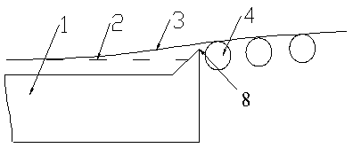
[0034] Such as figure 2 As shown, the structure is a structural schematic diagram of the prior art. Compared with the prior art, the present invention, through the design of the edge, diversion tank and recovery box, recycles tin liquid and places tin addition outside the tank, effectively avoiding the The intrusion of outside air and the structure of the edge and the tra...
PUM
 Abstract
Description
Claims
Application Information
 - R&D Engineer
- R&D Manager
- IP Professional
- Industry Leading Data Capabilities
- Powerful AI technology
- Patent DNA Extraction
Browse by: Latest US Patents, China's latest patents, Technical Efficacy Thesaurus, Application Domain, Technology Topic, Popular Technical Reports.
© 2024 PatSnap. All rights reserved.Legal|Privacy policy|Modern Slavery Act Transparency Statement|Sitemap|About US| Contact US: help@patsnap.com


