Slab lens for air imaging and air imaging system

A flat lens, air technology, applied in the optical field, can solve problems such as affecting the viewing angle of the picture, low imaging clarity, reducing the depth of field of air imaging, etc., to achieve the effect of improving the clarity, improving the imaging clarity, and reducing the dispersion speckle

Pending Publication Date: 2020-02-14
ZHEJIANG PRISM HOLOGRAPHIC TECH CO LTD
View PDF0 Cites 4 Cited by
  • Summary
  • Abstract
  • Description
  • Claims
  • Application Information

AI Technical Summary

Problems solved by technology

[0002] The flat plate lens for air imaging generally adopts a strip reflector or a dihedral reflector, and the strip-shaped light-transmitting body is coated with a reflective surface to form a strip-shaped reflector, and several strip-shaped reflectors are spliced ​​side by side to form a light The waveguide lens array, two optical waveguide lens arrays are stacked in an orthogonal manner to form a whole piece of optical imaging element, but in each existing optical waveguide lens array, the width of each strip-shaped reflector is equal, and the light source The distance from the reflective surface to each strip reflector is not equal, and a light spot will be formed after passing through each strip reflector, and all the light spots will be superimposed to form spherical aberration, and the spherical aberration will reduce the depth of field of air imaging, and at the same time It will cause low imaging clarity. In the optical mirror group, the combination of convex lens and concave lens is often used to improve the clarity, but the combination of convex lens and concave lens in the air imaging device will seriously affect the viewing angle of the picture.

Method used


Image

  • Slab lens for air imaging and air imaging system
  • Slab lens for air imaging and air imaging system
  • Slab lens for air imaging and air imaging system

Examples


Embodiment 1

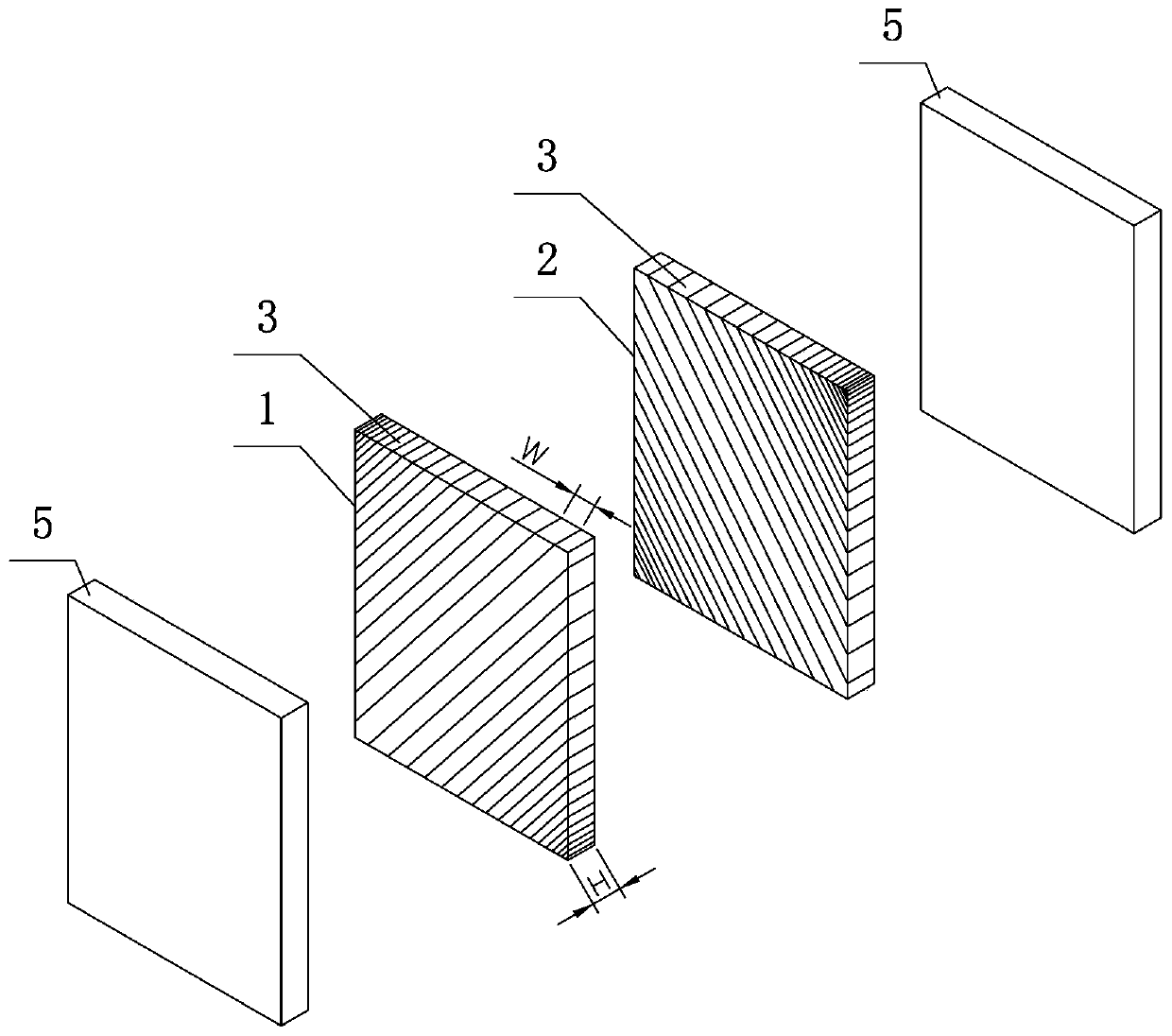
[0026] refer to figure 1 It is embodiment one of a flat plate lens for air imaging of the present invention, a flat plate lens for air imaging, comprising a first optical waveguide lens array 1 and a second optical waveguide lens array 2 arranged in parallel, each optical waveguide lens array Comprising a plurality of reflective mirrors 3 arranged in parallel, the reflective mirrors 3 in the first optical waveguide mirror array 1 and the reflective mirrors 3 in the second optical waveguide mirror array 2 are arranged orthogonally, and the width W of the reflective mirrors 3 is determined by The center of the optical waveguide lens array is reduced to the edge. The so-called center of the optical waveguide lens array is the reflective lens 3 in the middle of the entire lens array, and its width is the widest. The farther away from it is the reflective lens 3. small in figure 1 The reflector in the middle should be the one closest to the diagonal, so that the waveguide structur...

Embodiment 2

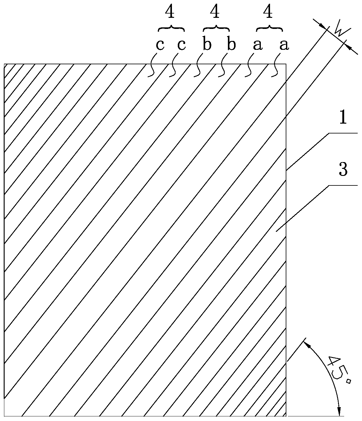
[0033] The difference from Embodiment 1 is that at least two adjacent reflective mirrors 3 with equal width form a lens group 4, and the number of reflective mirrors in each group of lens groups can be equal or unequal. In this embodiment, each group of mirrors In the group 4 are two reflecting mirrors 3 with the same width and arranged in parallel. Such as figure 2 Among them, a, b, and c respectively represent reflectors 3 with different widths, and the width a>b>c, two pieces in one group can also form a slit waveguide structure to reduce spherical aberration. This setting can ensure the effect of reducing spherical aberration while reducing manufacturing costs.

[0034] In addition to the arrangements of the mirrors in the above two embodiments, the width of the mirrors from the center to the edge can also be arranged in other regular or irregular ways, as long as the width of the mirrors far away from the center is reduced relative to the width of the mirrors near the c...


PUM

PropertyMeasurementUnit
Widthaaaaaaaaaa
Thicknessaaaaaaaaaa

Abstract

The invention discloses a slab lens for air imaging, comprising a first optical waveguide lens array and a second optical waveguide lens array arranged in parallel, wherein each optical waveguide lensarray comprises a plurality of reflective lenses arranged in parallel, the reflective lenses in the first optical waveguide lens array is orthogonal to the reflective lenses in the second optical waveguide lens array, and the widths of the reflective lenses are reduced from the center to the edge of the optical waveguide lens array. An air imaging system is also disclosed, comprising a light source and a slab lens, wherein the slab lens is any of the above slab lenses for air imaging. The slab lens has the advantages: compared with an ordinary strip reflector, the diffuse spot is smaller after using this solution, so the spherical aberration is smaller, the imaging depth of field is larger, the imaging clarity is effectively improved, this design does not change the size of the original slab lens, and the slab lens can be directly replaced to the original air imaging equipment.

Description

technical field [0001] The invention relates to the field of optical technology, in particular to a flat lens for air imaging and an air imaging system. Background technique [0002] The flat plate lens for air imaging generally adopts a strip reflector or a dihedral reflector, and the strip-shaped light-transmitting body is coated with a reflective surface to form a strip-shaped reflector, and several strip-shaped reflectors are spliced ​​side by side to form a light The waveguide lens array, two optical waveguide lens arrays are stacked in an orthogonal manner to form a whole piece of optical imaging element, but in each existing optical waveguide lens array, the width of each strip-shaped reflector is equal, and the light source The distance from the reflective surface to each strip reflector is not equal, and a light spot will be formed after passing through each strip reflector, and all the light spots will be superimposed to form spherical aberration, and the spherical...

Claims


Application Information

Patent Timeline
IPC IPC(8): G02B5/136G02B27/00G09F19/16
CPCG02B5/136G02B27/0025G09F19/16
Inventor 黄坤张峰
Owner ZHEJIANG PRISM HOLOGRAPHIC TECH CO LTD
Why Eureka
Try Eureka