
A large field of view laser warning method and system

A laser warning, large field of view technology, applied in the field of laser, can solve the problems of enhancement, not improving sensitivity, and high cost

Active Publication Date: 2020-10-23
HUBEI HUAZHONG PHOTOELECTRIC SCI & TECH
View PDF7 Cites 2 Cited by
  • Summary
  • Abstract
  • Description
  • Claims
  • Application Information

AI Technical Summary

Problems solved by technology

[0004] The traditional scattering and interception laser warning device adopts the method of improving the sensitivity of the photoelectric conversion module. The photoelectric conversion module adopts the method of signal amplification and comparator threshold value judgment. The comparator threshold value is greater than the voltage value of the noise signal. The noise is mainly composed of two parts: one is Circuit noise, the second is background light noise, circuit noise includes photodetector noise, dark current noise, etc., the circuit noise can be reduced as much as possible by optimizing devices and optimizing circuit layout; but the background light noise is the noise of solar radiation, the more sunlight Stronger, the closer the incident angle is to 90°, the greater the optical noise. Therefore, when the laser warning field of view is larger, the optical noise is also stronger, and the false alarm rate is also increased. Sensitivity improvement is limited
At the same time, there are two main ways to improve the sensitivity of traditional photoelectric conversion modules: 1. Use laser detectors with better performance. If imported devices are used, the cost will be higher; The laser signal output by the device is amplified multiple times (generally three levels), so that the signal amplitude exceeds the threshold circuit, and then transmitted to the signal processing circuit; therefore, the noise signal is also amplified while the laser signal is amplified, causing the threshold circuit to set the amplitude If it is too high, it will not improve the sensitivity
At the same time, since the field of view of the collected laser light becomes larger and has a converging effect, it is equivalent to increasing the energy of the incident laser light, but at the same time the background interference (sunlight interference) is also enhanced. Since the inherent electrical noise of the circuit has not changed, therefore, at night and at noon When under strong sunlight, the range of sunlight interference noise becomes wider, and the method of using a fixed threshold is no longer applicable

Method used

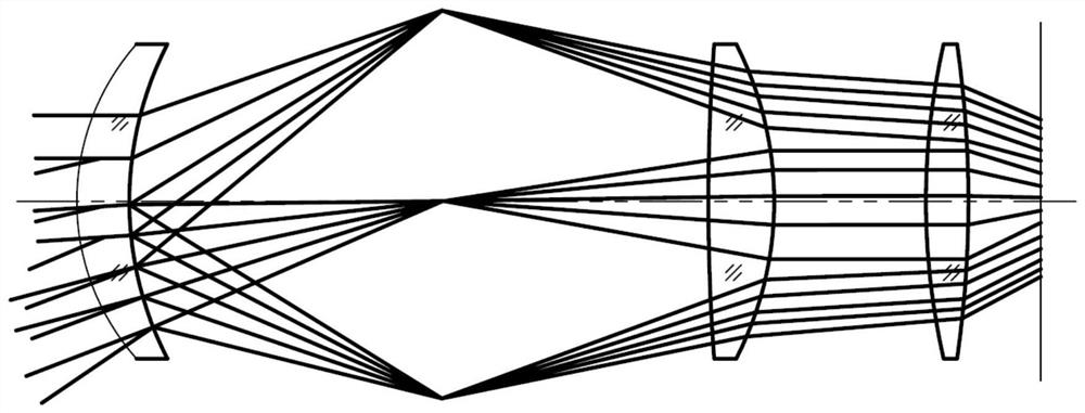

Image

  • A large field of view laser warning method and system
  • A large field of view laser warning method and system

Examples


Embodiment Construction

[0027] In order to make the object, technical solution and advantages of the present invention clearer, the present invention will be further described in detail below in conjunction with the accompanying drawings and embodiments. It should be understood that the specific embodiments described here are only used to explain the present invention, not to limit the present invention.

[0028] In addition, the technical features involved in the various embodiments of the present invention described below can be combined with each other as long as they do not constitute a conflict with each other. The present invention will be further described in detail below in combination with specific embodiments.

[0029] A laser warning method with a large field of view, the specific steps are: receiving an optical signal with a large field of view and converting it into an electrical signal; converting the electrical signal into a first pulse signal, and performing P The data is preprocesse...


PUM


Abstract

The invention discloses a laser alarming method and system for a large field of view. The laser alarming method comprises the detailed steps that an optical signal from the large field of view is received and converted into an electrical signal; the electrical signal is converted into a first pulse signal, and a second pulse signal is obtained by preprocessing P data from every P cycle of the first pulse signal, that is, after maximum M data and minimum N data in the P data are removed and then an average value is extracted to obtain a dynamic threshold D1; a first average value D2 is obtainedthrough extraction of maximum Q data and the average value; when the first average value D2 is less than the dynamic threshold D1 of S times of a first reference value, the fact that a laser signal is not included in the P data is confirmed, and the second pulse signal is not transmitted; a value, below the dynamic threshold D1, in the P data of the first pulse signal is set to be zero to obtaina second pulse signal; and the second pulse signal with the pulse width exceeding a first preset threshold T1 is decoded and output, and thus a false alarming rate of the laser alarming method for thelarge field of view is lowered.

Description

technical field [0001] The invention belongs to the field of lasers, and in particular relates to a large field of view laser warning method and system. Background technique [0002] The core of a laser-guided weapon is a laser semi-active guidance system, which consists of a laser seeker on the bomb and a laser target indicator outside the bomb. The laser target indicator emits a laser coded signal to the target and relies on the diffuse reflection signal of the target to guide the guidance. The weapon attacks the target. In order to ensure that the guided weapon can correctly identify the target indicated by its own side in a complex battlefield environment, the guidance signal emitted by the indicator is coded according to the preset code of the system. [0003] As an important part of the field of photoelectric countermeasures, the laser warning device directly affects the battlefield survival of the protected target. When the laser-guided weapon strikes an important tar...

Claims


Application Information

Patent Timeline
Patent Type & Authority Patents(China)
IPC IPC(8): F41H11/02
CPCF41H11/02
Inventor 安伟光李新火向泽湖张文中李宏宇吴伟林刘伟东
Owner HUBEI HUAZHONG PHOTOELECTRIC SCI & TECH
Learn More