High-efficient solar photovoltaic battery condensation device
A photovoltaic cell and concentrating device technology, which is applied in the field of solar photovoltaic cell devices and high-efficiency solar photovoltaic cell concentrating devices, can solve the problems of difficult Fresnel lens processing technology, limited light concentrating efficiency, and difficult processing, etc. The effect of simple structure, small beam dispersion and convenient processing
- Summary
- Abstract
- Description
- Claims
- Application Information
AI Technical Summary
Problems solved by technology
Method used
Image
Examples
Embodiment 1-1
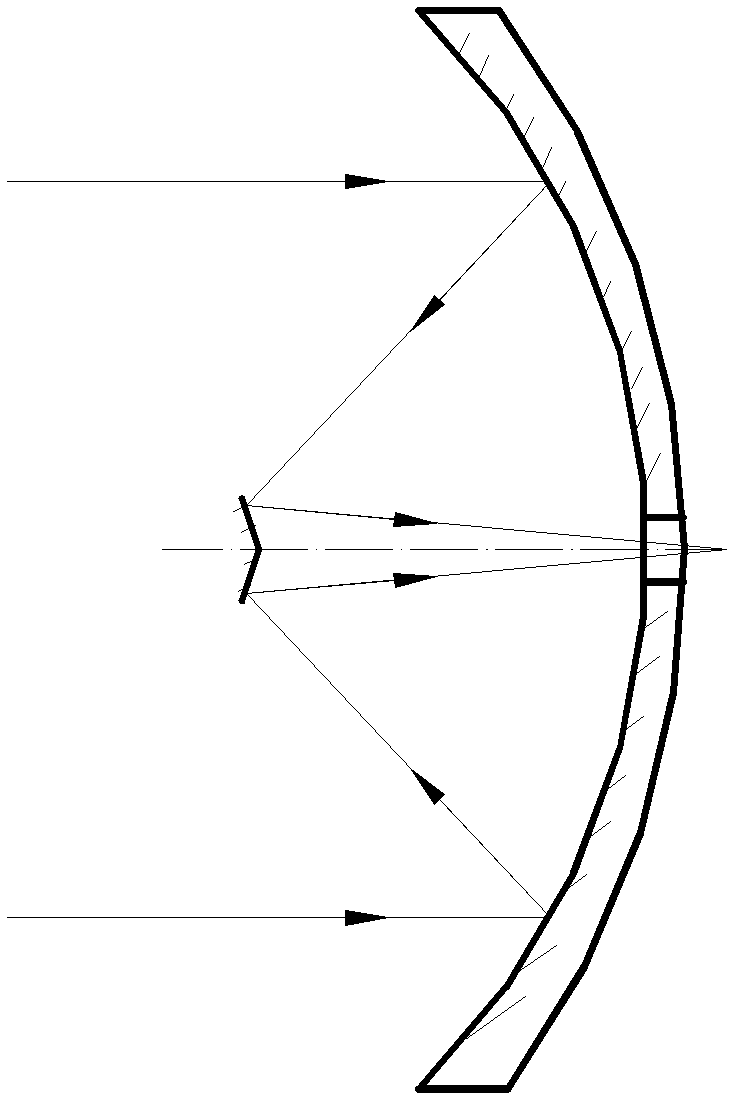
[0050] The mirror surface of the primary reflector 1 is a symmetrical paraboloid or a quadric surface or a spherical surface, and the mirror surface of the secondary reflector 2 is a symmetrical paraboloid or a quadric surface or a spherical surface; the Cassegrain type teleconcentrator The focal plane of the light combination system is located at the rear side of the main reflector 1, and the center of the main reflector 1 is provided with a light-transmitting hole, and the light-receiving surface of the solar photovoltaic cell device 3 is located at the rear side of the light-transmitting hole and is located in the Cassegrain-type telescope. At or near the location of the focal plane of the far-concentrating combination system, the solar photovoltaic cell device 3 is composed of a single solar photovoltaic cell with a small light-receiving area, high conversion efficiency, and good heat resistance.
[0051] The mirror surfaces of the primary reflector 1 and the secondary refl...
Embodiment 1-2
[0061] The difference between the high-efficiency solar photovoltaic cell concentrating device provided in this embodiment and Embodiment 1-1 is that: the number of the concentrating units is multiple, the optical axes of each concentrating unit are parallel to each other, and the plurality of concentrating units The sub-reflectors 2 are pasted at different positions on the rear side of the same transparent optical glass plate.
[0062] Such as Figure 7 and Figure 8 Shown are 9 identical light-gathering units designed in the above-mentioned embodiment 1-1 at 1m 2 Schematic diagram of the combined optics of the whole machine. The optical axes of each concentrating system need to be adjusted to be parallel to each other. Due to the use of a unified protective glass, the more complex processing of mechanical parts for fixing is avoided, and the production cost can be reduced.
Embodiment 2-1
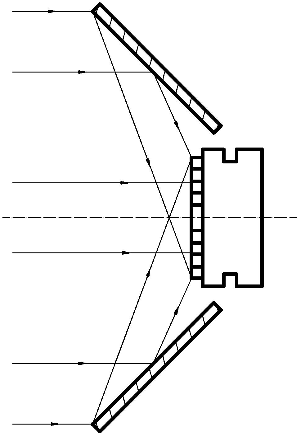
[0064] The mirror surface of the main reflector 1 is preferably a cylindrical paraboloid or a quadric surface or a spherical surface, and the mirror surface of the secondary reflector 2 is preferably a cylindrical paraboloid or a quadric surface or a spherical surface. The central axes of the cylinders of the reflector 2 are parallel to each other; the focal plane of the Cassegrain type telescopic concentrator system is located between the primary reflector 1 and the secondary reflector 2; the light-receiving surface of the solar photovoltaic cell device 3 is located on the card Between the focal plane of the Segren type telescopic concentrating combination system and the main reflector 1; the solar photovoltaic cell device 3 is composed of two or more light-receiving areas with large (generally greater than 30×30mm), low photoelectric conversion efficiency and durability. Solar photovoltaic cells with poor thermal performance are arranged along a direction parallel to the cent...
PUM
 Abstract
Description
Claims
Application Information
 - R&D
- Intellectual Property
- Life Sciences
- Materials
- Tech Scout
- Unparalleled Data Quality
- Higher Quality Content
- 60% Fewer Hallucinations
Browse by: Latest US Patents, China's latest patents, Technical Efficacy Thesaurus, Application Domain, Technology Topic, Popular Technical Reports.
© 2025 PatSnap. All rights reserved.Legal|Privacy policy|Modern Slavery Act Transparency Statement|Sitemap|About US| Contact US: help@patsnap.com


