
Top pipe work pit supporting method

A working pit and pipe jacking technology, which is applied in excavation, foundation structure engineering, sheet pile wall, etc., can solve the problems of complex underground conditions, narrow working space, unfavorable mechanical pipe jacking equipment and pipe hoisting space requirements, etc., and achieve site geology Good adaptability, reduced construction investment, good support effect

Inactive Publication Date: 2020-02-14
成都市市政工程设计研究院有限公司
View PDF6 Cites 3 Cited by
  • Summary
  • Abstract
  • Description
  • Claims
  • Application Information

AI Technical Summary

Problems solved by technology

[0004] Especially for working pits in urban environments, there are many surrounding structures and complex underground conditions. For ultra-deep working pits, cast-in-place piles and internal support structure systems are used. Although the support is reliable, the working space is narrow due to the influence of the internal support system. It is not conducive to the hoisting space requirements of mechanical pipe jacking equipment and pipe installation

Method used


Image

  • Top pipe work pit supporting method
  • Top pipe work pit supporting method
  • Top pipe work pit supporting method

Examples


Embodiment

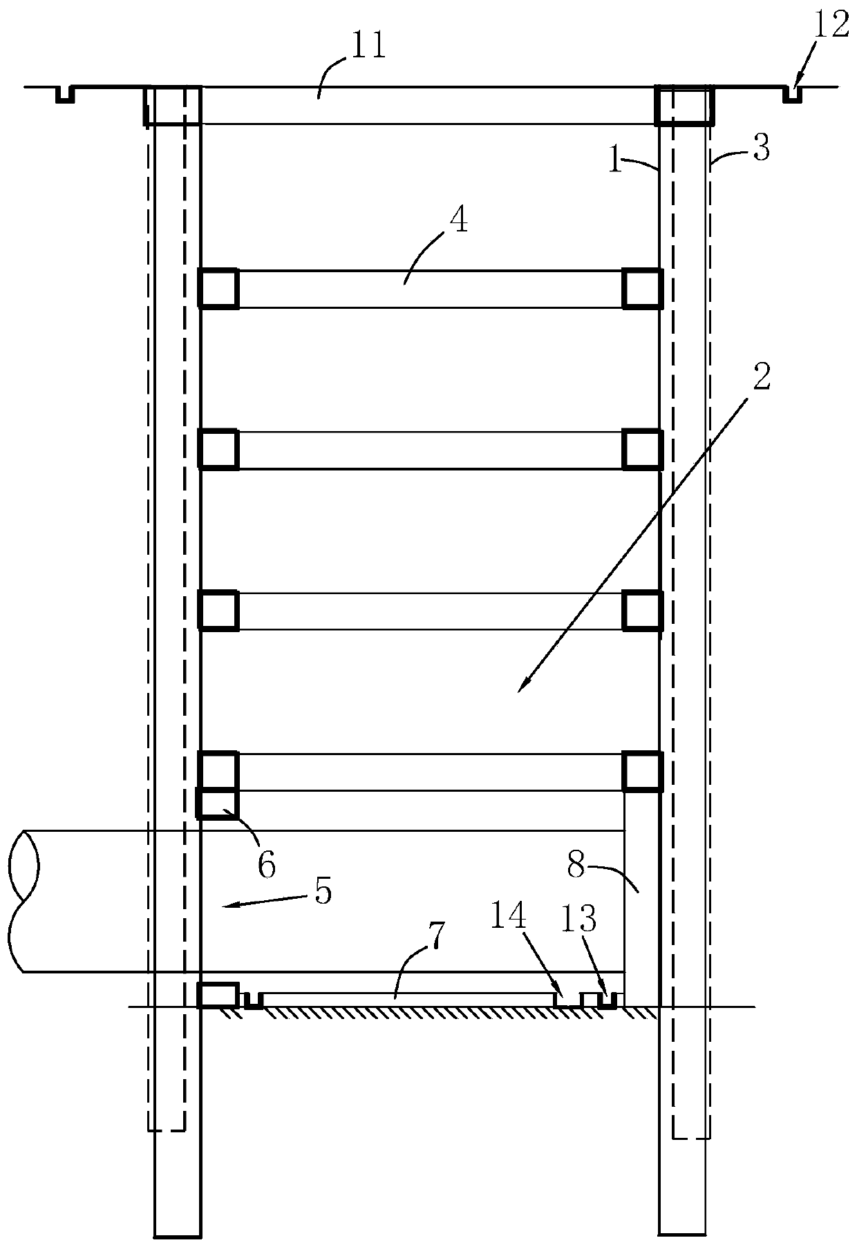
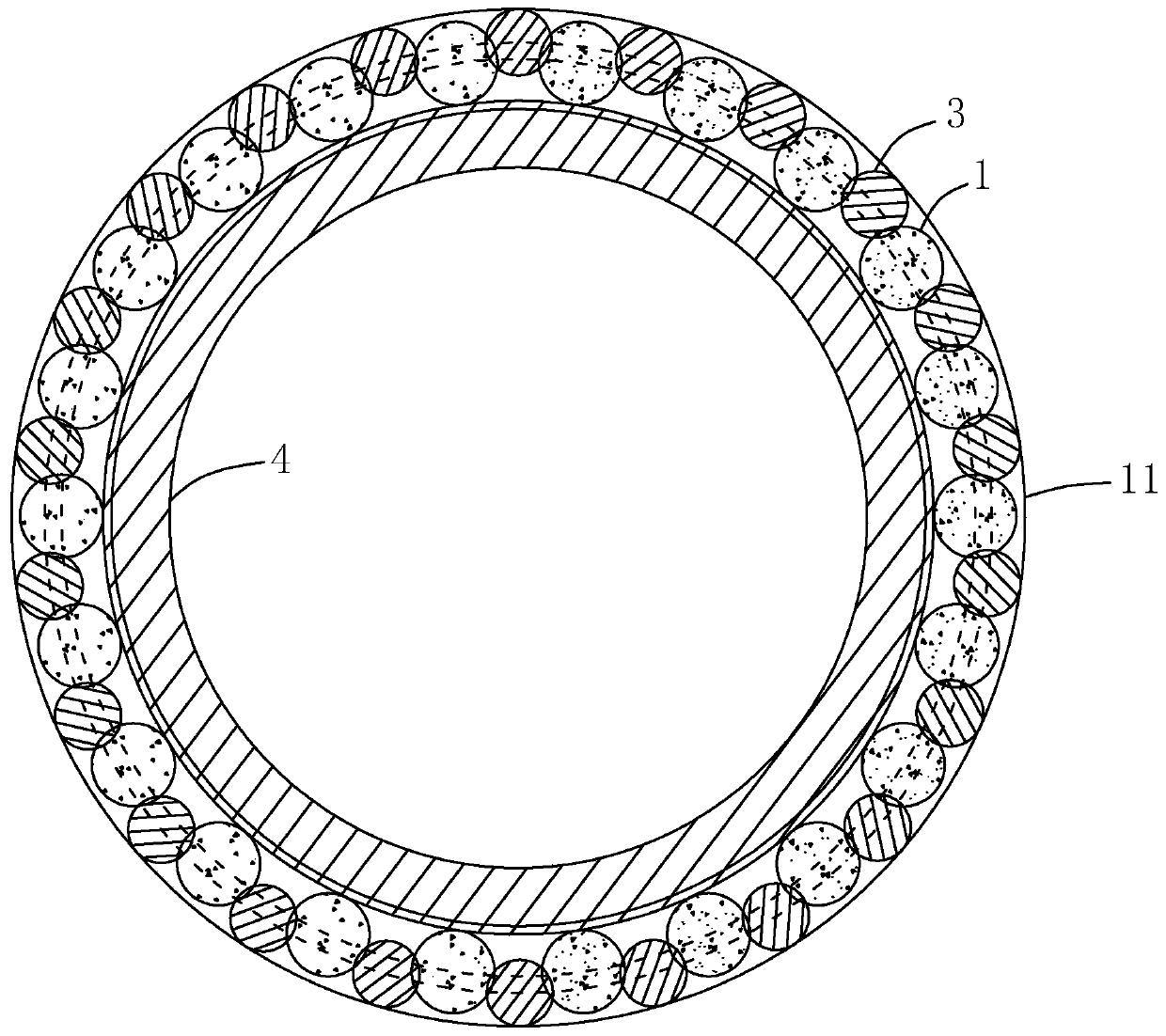
[0038] combine figure 1 with figure 2 , the working pit support structure for pipe jacking construction, including cast-in-situ pile 1, high-pressure jet water-stop pile 3, ring beam 4 and crown beam 11. The cast-in-place pile 1 surrounds the working pit 2 for pile-interval construction to form an annular pile row, and a high-pressure jet water-stop pile 3 is constructed between two adjacent cast-in-place piles 1, and the high-pressure jet water-stop pile 3 is engaged with the cast-in-place pile 1. Form a closed water-stop curtain. Simultaneously, the annular crown beam 11 is poured by formwork at the top of the water-stop curtain. The earth in the working pit 2 is excavated in layers. After the excavation reaches the design elevation of each layer, the construction of the ring beam 4 is carried out through the formwork, and the ring beam 4 is poured together with the water-stop curtain by inserting ribs.

[0039] Such as figure 1 As shown, in the working pit 2, the groun...


PUM


Abstract

The invention relates to a top pipe work pit supporting method. The method includes the following steps that firstly, construction preparation is made, field leveling is conduced according to the design elevation, setting out of pouring piles is conducted, pile spacing construction is conducted around a work pit, and ring-shaped row piles are formed; secondly, a high-pressure grouting water stop pile is constructed between every two adjacent pouring piles according to the geology and underwater distribution condition so that the high-pressure grouting water stop piles can be engaged with the pouring piles, and a closed water stop curtain is formed; thirdly, earthwork layered excavation is conducted in the work pit, after excavation is conducted till the design elevation of each layer is reached, ring beam construction is conducted, after ring beam construction of each layer reaches the design strength, excavation of the next layer of earthwork is conducted, and excavation is conductedtill the bottom of the work pit is reached; and fourthly, grouting and strengthening are conducted on the hole entering ground of a top pipe to form a hole inner lining wall, meanwhile, the position for the top pipe to enter the hole is reserved, cushion layer and rear seat wall combustion is conducted, top pipe equipment installation is conducted, and work pit construction is completed. The top pipe work pit supporting method has the beneficial effects that the structure is reliable, and top pipe construction is facilitated.

Description

technical field [0001] The invention relates to the technical field of foundation pit support, in particular to a method for supporting pipe jacking working pits. Background technique [0002] At present, in the construction of rainwater pipelines or sewage pipelines in municipal engineering, the pipe jacking method is usually used for construction. The jacking and burial of the pipeline requires a working space provided by the shaft, that is, a working pit. Under the limited space of the site, support measures must be taken for the working pit to ensure the safety of the earthwork excavation of the shaft and the subsequent pipeline construction. [0003] In the existing technology, the support form of the working pit at this stage is mainly determined by the pipe jacking process and the geological conditions of the site. For the hand-dug pipe jacking process, the equipment in the pit is relatively simple, and the requirements for the clearance of the top pit are not strict...

Claims


Application Information

Patent Timeline
IPC IPC(8): E02D17/08E02D5/46E02D5/34E02D19/12E02D9/00E02D19/08E02D19/10
CPCE02D5/34E02D5/46E02D9/00E02D17/08E02D19/08E02D19/10E02D19/12
Inventor 余波
Owner 成都市市政工程设计研究院有限公司
Learn More