
A push device and interventional delivery system

A push device and core wire technology, applied in the field of medical devices, can solve problems such as increasing patient pain, failure of interventional surgery, increasing medical risk of therapy, etc., and achieve the effect of reducing treatment risk

Active Publication Date: 2020-07-14
上海介入医疗器械有限公司
View PDF8 Cites 0 Cited by
  • Summary
  • Abstract
  • Description
  • Claims
  • Application Information

AI Technical Summary

Problems solved by technology

However, the current clinical application of the pushing device often encounters the challenge of how to balance the flexibility and stiffness of the pushing device.
[0007] After the pushing device enters the human body, due to different human body structures, even with the same operation, the resulting movement may be unpredictable, which will have a corresponding impact on the implanted device
For example, before the implanted device is separated from the pushing device, the implanted device may be kept in the implanted position under the influence of external forces such as pulling force or pushing force generated by the rigidity of the pushing device itself. During or after the separation of the implanted device and the pushing device , the external force of the above-mentioned push device on the implanted device changes or loses, and the implanted device will deviate greatly from the most suitable implanted position or even fall off, resulting in the failure of the interventional operation
Increasing the flexibility of the push device can help alleviate the above problems, but it will increase the difficulty of pushing the implanted device to move in the transvascular access
[0008] The above problems are the difficulties to be faced by various treatment schemes using endovascular interventional technology, which may not only increase the suffering of patients, but also increase the medical risks of this type of therapy

Method used


Image

  • A push device and interventional delivery system
  • A push device and interventional delivery system
  • A push device and interventional delivery system

Examples


Embodiment 2

[0047] Such as Figure 6 As shown, the second embodiment of the push device adds an operating part 30 located at the proximal end of the push main body 10 on the basis of the first embodiment of the push device, so the second embodiment of the push device includes all the technical features of the first embodiment of the push device , and the second embodiment of the pushing device enables the operator to conveniently operate the movement of the proximal end of the inner layer core wire 12 in the axial direction of the pushing device and the rotation of the whole pushing device through the operating part 30, thereby correspondingly controlling the movement of the pushing device Stiffness and softness, and control of the detachable connection between the distal end of the instrument connection portion 20 and the implant instrument 40 .

[0048] Such as Figure 6 As shown, in the second embodiment of the pushing device, the instrument connection part 20, the pushing main part 1...


PUM


Abstract

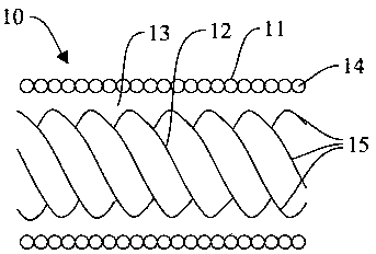
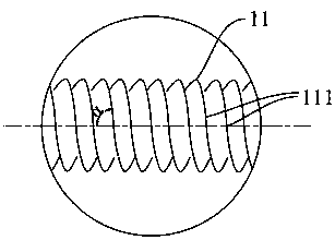
The invention provides a pushing device and an intervention transfer system comprising the pushing rod. The pushing device comprises a pushing body part which extends in the axial direction of the pushing device, and an apparatus connecting part arranged at the far end of the pushing body part, wherein the pushing body part comprises a hollow outer layer spring, an inner layer core wire arranged in the outer layer spring in a penetrating manner and an interlayer gap formed between the outer layer spring and the inner layer core wire; the outer layer spring and the inner layer core wire are fixed to the apparatus connecting part at the far end of the pushing body part; and the outer layer spring and the inner layer core wire can realize relative slippage along the axial direction of the pushing device at the near end of the pushing body part. According to the pushing device disclosed by the application, the rigidity and the flexibility of the pushing device can be adjusted, so that influence of the pushing device on a transplanting apparatus is more controllable, reliably maintaining the transplanting apparatus to an implantation position is facilitated, and the treatment risk of interventional therapy is reduced.

Description

technical field [0001] The invention relates to the field of medical instruments. [0002] The invention particularly relates to a push device. [0003] The present invention also particularly relates to an interventional delivery system comprising the above-mentioned pushing device. Background technique [0004] Interventional therapy relies on the guidance of medical imaging equipment, and uses puncture needles, catheters and other interventional equipment to diagnose and treat diseases. Interventional therapy has become the third major clinical treatment alongside medical treatment and surgical treatment. There are many interventional techniques, which can be divided into endovascular interventional techniques and non-vascular interventional techniques. [0005] Intravascular interventional technique is the application of selective or superselective angiography. After the location, nature, scope and degree of the lesion are determined first, embolization, intravascular...

Claims


Application Information

Patent Timeline
Patent Type & Authority Patents(China)
IPC IPC(8): A61B17/12A61B17/00A61F2/966A61F2/24A61F2/01
CPCA61B17/0057A61B17/12022A61B2017/00623A61B2017/1205A61F2/01A61F2/24A61F2/966
Inventor 汤亮李瑞闫伟龚善石赵丹儒
Owner 上海介入医疗器械有限公司
Learn More